
Liquid ejecting head, liquid ejecting unit, and liquid ejecting apparatus

A technology of liquid ejection head and ejection device, which is applied in the directions of printing device, inking device, printing, etc., can solve the problems of low bubble discharge, inability to eject ink, and inability to suppress the sinking of liquid components.

Active Publication Date: 2011-10-19
SEIKO EPSON CORP
View PDF4 Cites 16 Cited by
  • Summary
  • Abstract
  • Description
  • Claims
  • Application Information

AI Technical Summary

Problems solved by technology

[0005] However, in the ink jet recording head described in Patent Document 1, it is difficult to introduce the ink into the downstream circulation path, so the discharge performance of the bubbles is low, and there is also a problem that the sinking of the liquid component cannot be suppressed.
Furthermore, in such an ink jet recording head, there is a problem that ink cannot be uniformly ejected from all the nozzles when ink is ejected.
In addition, not only in the liquid ejecting apparatus using the inkjet recording head, but also in the liquid ejecting apparatus using the liquid ejecting head ejecting liquid other than ink, there is such a problem

Method used


Image

  • Liquid ejecting head, liquid ejecting unit, and liquid ejecting apparatus
  • Liquid ejecting head, liquid ejecting unit, and liquid ejecting apparatus
  • Liquid ejecting head, liquid ejecting unit, and liquid ejecting apparatus

Examples


Embodiment Construction

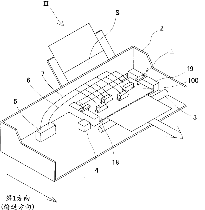
[0020] refer to Figure 1 to Figure 6 The liquid ejecting device of the present invention will be described. The ink jet recording apparatus of the present embodiment is a so-called line ink jet recording apparatus, in which a liquid ejecting head is fixed to the main body of the ink jet recording apparatus, and recording is performed by feeding recording paper or the like in a direction orthogonal to the nozzle row direction. media to print on the recording medium. figure 1 The illustrated ink jet recording apparatus III includes a head unit 1 , an apparatus main body 2 , a paper feed roller 3 as an example of a moving mechanism, and a control unit 4 .

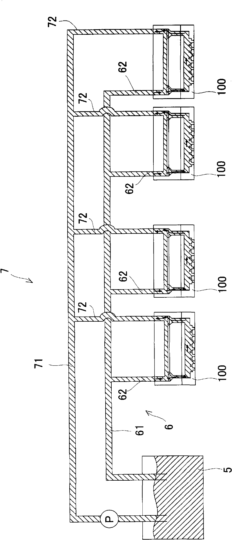
[0021] The head unit 1 includes a frame member 19 that is attached to a base plate 18 that holds a head group composed of a plurality of liquid ejection heads (hereinafter referred to as heads) 100 (in addition, in figure 1 Four heads 100 constitute each head group), and the head unit 1 is fixed to the apparatus main body...


PUM


Abstract

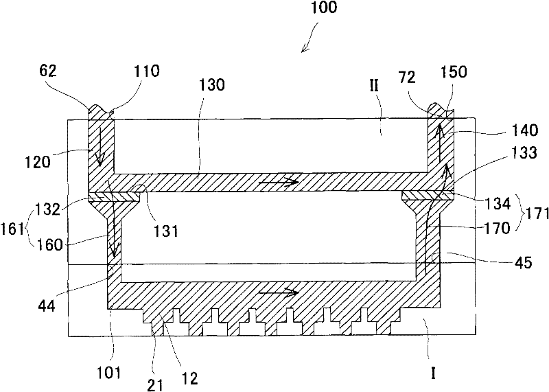
The invention provides a liquid ejecting head including a circulation path which has a more uniform ejection property, a liquid ejecting unit including the corresponding liquid ejecting head, and a liquid ejecting apparatus. The liquid ejecting head comprises: a plurality of nozzle openings that eject a liquid; a first flow path that is communicated with the plurality of nozzle openings and in which the liquid is circulated; a supply path that supplies the liquid to the first flow path from an outside; a recovery path that recovers the liquid from the first flow path to the outside; a first filter that is provided in the supply path; a second filter that is provided in the recovery path; and a second flow path that connects the supply path provided in an upstream side of the first filter and the recovery path provided in downstream side of the second filter, wherein a recovery side flow path between the first flow path and the second flow path of the recovery path has a flow path resistance which is lower than flow path resistance of the supply side flow path between the first flow path and the second flow path of the supply path. The liquid ejecting head unit and the liquid ejecting apparatus comprise the liquid ejecting head.

Description

technical field [0001] The present invention relates to a liquid ejecting head, a liquid ejecting unit, and a liquid ejecting device. Background technique [0002] Conventionally, in an ink jet recording apparatus, which is an example of a liquid ejecting apparatus, there is known a circulation type in which an ink tank is provided separately from the ink jet recording head, and ink is circulated between the ink tank and the ink jet recording head. of ink jet recording devices. (For example, refer to Patent Document 1). [0003] In the ink jet recording apparatus described in Patent Document 1, one outgoing pipe and one return pipe are provided in the ink tank, and the outgoing pipe and the return pipe are branched to supply ink to the respective recording heads. Each recording head is formed with a circulation path upstream of the filter and a circulation path downstream of the filter. By providing these two circulation paths, the discharge performance of air bubbles is i...

Claims


Application Information

Patent Timeline
Patent Type & Authority Applications(China)
IPC IPC(8): B41J2/14B41J2/045
CPCB41J2/14233B41J2/1707B41J2/17563B41J2/18B41J29/02B41J2202/12
Inventor 植泽晴久
Owner SEIKO EPSON CORP
Learn More