Liquid ejecting head, liquid ejecting head unit, and liquid ejecting apparatus

A technology of a liquid ejection head and an ejection device, which is applied in the field of inkjet recording devices and liquid ejection devices, and can solve the problems of hindering the displacement of piezoelectric elements, offset of ink landing position, and decrease of rigidity of partition walls, etc., and achieve the goal of suppressing the ink landing position Offset, suppression of voltage drop, and effects of improving print quality

Active Publication Date: 2011-10-12
SEIKO EPSON CORP
View PDF12 Cites 4 Cited by
  • Summary
  • Abstract
  • Description
  • Claims
  • Application Information

AI Technical Summary

Problems solved by technology

[0008] However, in the case where the first electrode is formed as an individual electrode and the second electrode is formed as a common electrode as in Patent Document 1, a configuration in which the piezoelectric layer and the second electrode are continuously provided across a plurality of pressure generating chambers is considered, However, there is a problem that the continuous piezoelectric layer and the second electrode between adjacent piezoelectric elements hinder the displacement of the piezoelectric elements, so that the desired displacement characteristics cannot be obtained, that is, the generation of the so-called piezoelectric Component crosstalk (cross talk)
[0009] Therefore, when an opening is formed in the partition wall forming the pressure generating chamber without the piezoelectric layer and the second electrode, the rigidity of the partition wall decreases.
In particular, when the thickness of the partition wall becomes thinner due to the increase in the density of nozzle openings, there are problems that the rigidity of the partition wall is significantly reduced, and the partition wall is deformed due to the pressure fluctuation of the pressure generating chamber, so that the pressure fluctuation is transmitted to the phase. Adjacent pressure generation chambers, resulting in the so-called crosstalk of the partition wall that causes the ink landing position to shift or the ink ejection characteristics to decline.

Method used


Image

  • Liquid ejecting head, liquid ejecting head unit, and liquid ejecting apparatus
  • Liquid ejecting head, liquid ejecting head unit, and liquid ejecting apparatus
  • Liquid ejecting head, liquid ejecting head unit, and liquid ejecting apparatus

Examples


Embodiment approach 1

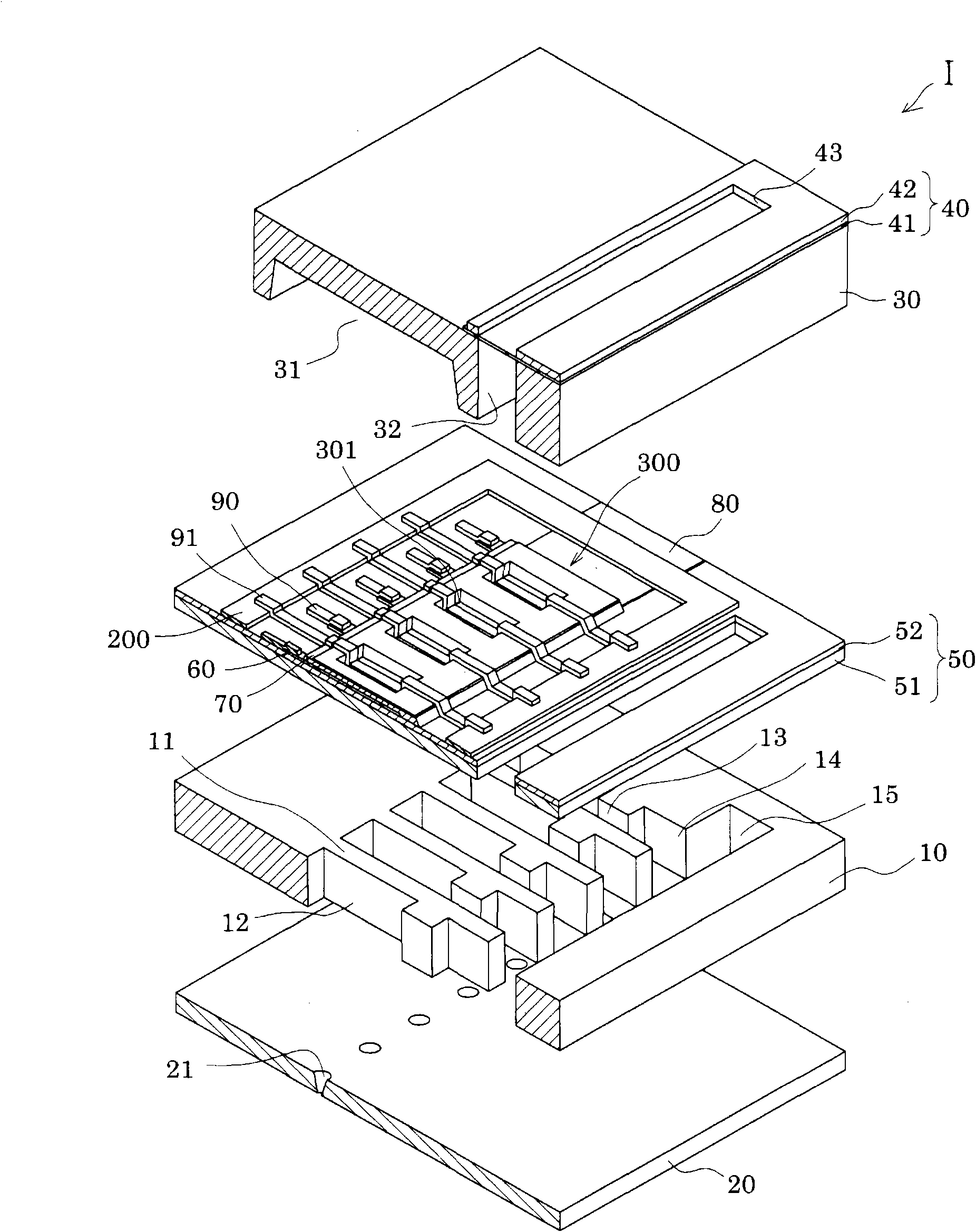
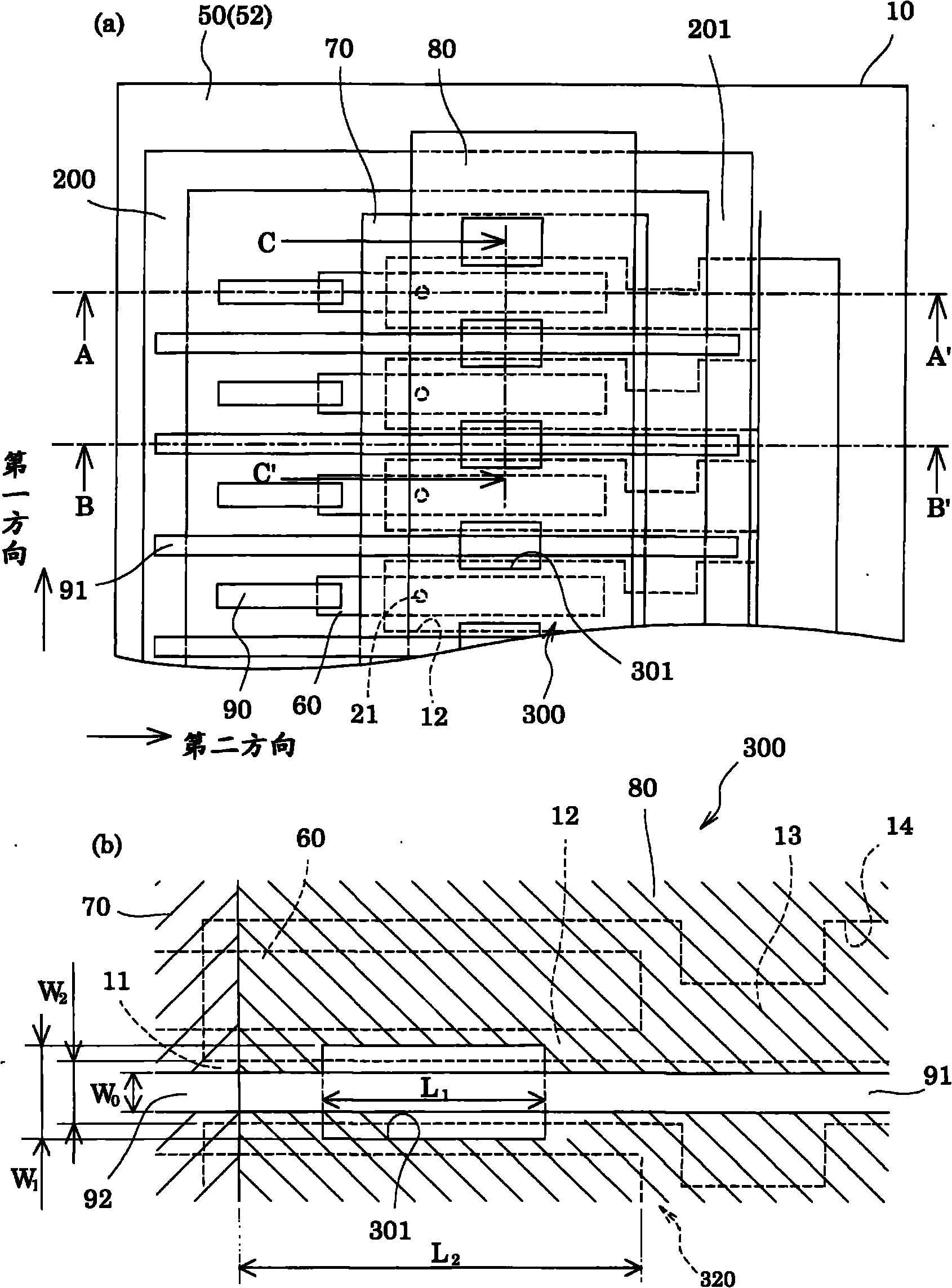
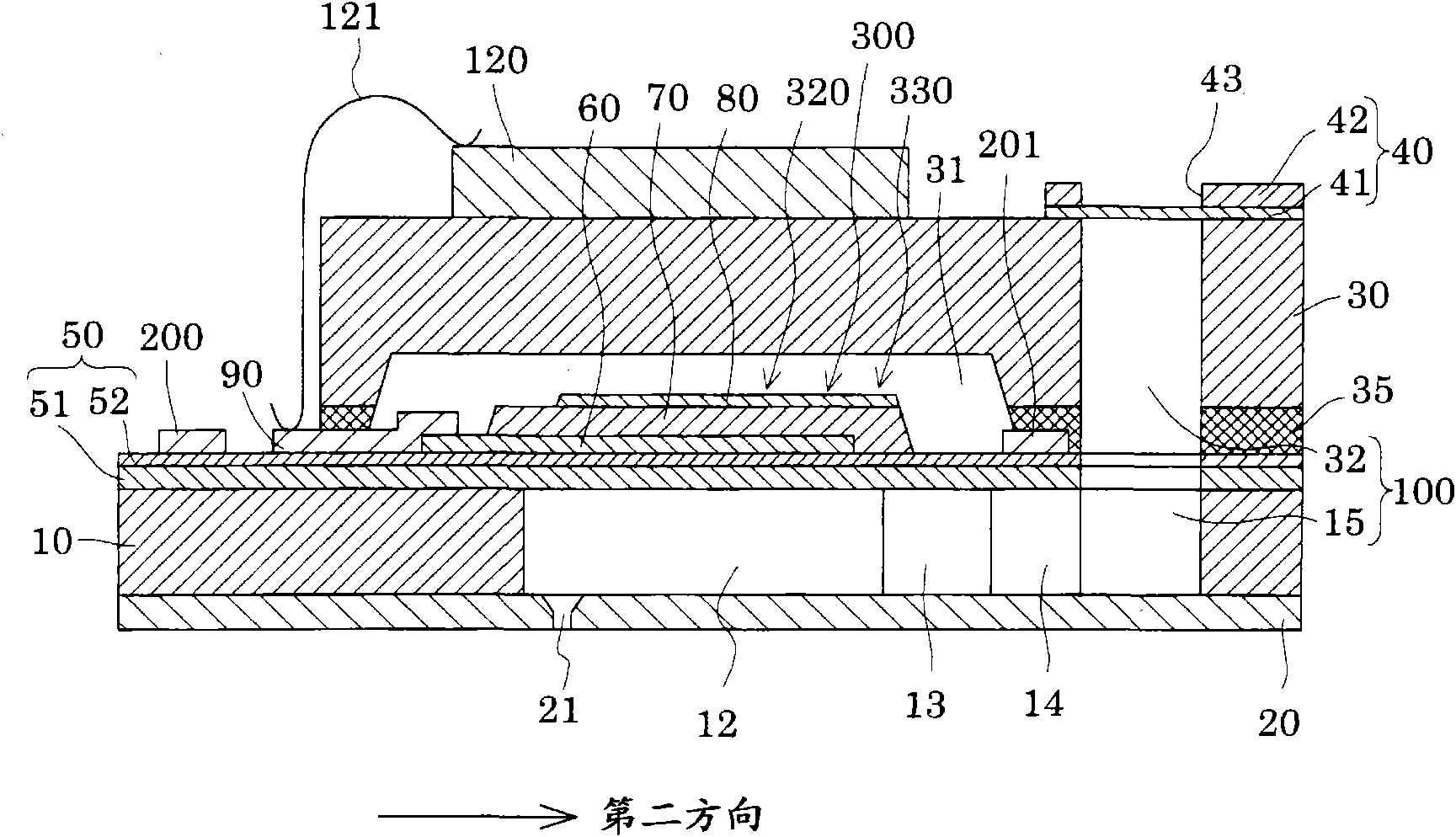
[0030] figure 1 It is an exploded perspective view of an ink jet recording head as an example of a liquid ejection head according to Embodiment 1 of the present invention, figure 2 It is a plan view and an enlarged view of main parts of the flow path forming substrate of the inkjet recording head, image 3 is along figure 2 A cross-sectional view of the line A-A', Figure 4 is along figure 2 The sectional view of the B-B' line, Figure 5 is along figure 2 The cross-sectional view of the line C-C'.

[0031] like figure 1 As shown, a plurality of pressure generating chambers 12 partitioned by partition walls 11 are arranged along the width direction (short side direction, the first direction in this embodiment) on the flow path forming substrate 10 constituting the inkjet recording head 1. In addition, ink supply channels 13 and communication channels 14 that communicate with the respective pressure generating chambers 12 are provided on the flow channel forming substra...

Embodiment approach 2

[0060] Image 6 It is a plan view of main parts of an ink jet recording head as an example of a liquid ejecting head according to Embodiment 2 of the present invention. In addition, the same reference numerals are assigned to the same components as in the first embodiment described above, and overlapping descriptions will be omitted.

[0061] like Image 6 As shown, in the present embodiment, the common lead electrode 91A includes a narrow portion 92 and a wide portion 93, the narrow portion 92 is provided in the opening 301 with a width narrower than the thickness of the partition wall 11, and the wide portion 93 is provided in the opening 301. The outer side of the opening 301 is provided with a width wider than the thickness of the partition wall 11 .

[0062] Thus, by providing the narrow portion 92 on the common lead electrode 91A, it is possible to prevent the common lead electrode 91A from obstructing the displacement of the piezoelectric body active part 320 (vibrati...


PUM


Abstract

The invention provides a liquid ejecting head, a liquid ejecting head unit, and a liquid ejecting apparatus, which can suppress a crosstalk between piezoelectric elements and through a partition wall, as well as a voltage drop, thereby suppressing deviation of ink droplet landing position and stabilizing liquid ejection characteristic, thus contributing to improving printing quality. The piezoelectric element includes a first electrode serving as an individual electrode, a piezoelectric layer, and a second electrode serving as a common electrode is attached on a face of a flow path substrate via a vibrating plate. A piezoelectric active portion defined by the first electrode and the second electrode serving as a substantial driver of the piezoelectric element is provided in a region opposing the pressure chamber. An opening formed by removing the second electrode and the piezoelectric layer is provided in a region of the piezoelectric element opposing the partition wall. A wiring electrode and the second electrode provided on the flow path substrate are connected via a common lead electrode provided on the piezoelectric active portion, and the common lead electrode is provided at least on the partition wall inside the opening.

Description

technical field [0001] The present invention relates to a liquid ejection head, a liquid ejection head unit, and a liquid ejection apparatus that eject liquid from nozzle openings, and in particular, to an ink jet type recording head that ejects ink as a liquid, an ink jet type recording head unit, and an ink jet type recording head. recording device. Background technique [0002] Among the liquid ejection heads, there is an inkjet type recording head in which a piezoelectric element is provided via a vibrating plate on one side of a flow path forming substrate, and pressure generating chambers partitioned by partition walls are arranged in a row on the flow path forming substrate, The pressure generating chamber communicates with the nozzle opening, and the piezoelectric element is driven to cause a pressure change in the pressure generating chamber to eject ink droplets from the nozzle opening. [0003] As such an ink jet recording head, there has been proposed an ink jet...

Claims


Application Information

Patent Timeline
Patent Type & Authority Applications(China)
IPC IPC(8): B41J2/045B41J2/135
CPCB41J2/14233B41J2202/11B41J2002/14241B41J2002/14491
Inventor 高岳
Owner SEIKO EPSON CORP
Why Eureka
Try Eureka