Moire method and measuring system for measuring the distortion of an optical imaging system

a technology of optical imaging and distortion measurement, applied in the field of aberration measurement, can solve the problems of reducing product yield, increasing production costs, and unable to obtain theoretical calculations for all optical properties, and achieve the effect of high measuring accuracy and fast measurement of distortion in a plurality of different image directions

Inactive Publication Date: 2006-03-28
CARL ZEISS SMT GMBH
View PDF15 Cites 16 Cited by
  • Summary
  • Abstract
  • Description
  • Claims
  • Application Information

AI Technical Summary

Benefits of technology

[0012]It is one object of the invention to provide a moiré method and a corresponding measuring system with the aid of which it is possible to measure distortion in a plurality of different image directions quickly and with high measuring accuracy.
[0035]For example, the displacement can be carried out in the direction of an angle bisector between the first and second directions of periodocity, and this corresponds to a diagonal direction in the case of mutually perpendicular directions of periodicity. However, it is preferred to perform relative displacement in a displacement direction which is not situated symmetrically between directions of periodicity. Different periodicity lengths of the phase shift signals assigned to the image directions result in this case in the directions of periodicity, particularly given identical grating constants. As a result, crosstalk between the various directional components is suppressed to such an extent that it is possible to achieve high measuring accuracy.
[0036]The relative displacement in a displacement direction situated asymmetrically between directions of periodicity can also be advantageous in the case of other multidimensional object / image patterns which are not parceled, for example when using object / image patterns with an (orthogonal or oblique-angled) crossedygrating, or an orthogonal or oblique-angled chessboard grating.
[0037]It is also possible for a relative displacement to be carried out in a temporally offset fashion in a first displacement direction assigned to the first direction of periodicity, and in a second displacement direction assigned to the second direction of periodicity. In particular, a complete signal can firstly be picked up in one displacement direction, and thereafter a complete signal can be picked up in the second displacement direction. It is also possible to alternate multiply between the displacement directions. It is possible for predetermined relative positions between the object pattern and image pattern in the first displacement direction and the second displacement direction to be set in different sequences in order in this way to obtain permutation of relative positions. Crosstalk between signals for different image directions can also be avoided thereby.

Problems solved by technology

An imaging optical with impermissibly high distortion can, for example, produce defects in integrated circuits, and this reduces the product yield in the case of semiconductor fabrication, thereby raising the production costs.
Such projection objectives have a complicated optical design with a multiplicity of imperfect lenses, which renders it impossible as a rule for all the optical properties to be derived from theoretical calculations.
A mechanically complicated measurement setup is required for this purpose.
However, it is necessary to intervene in the projection objective in order to install a suitable pupil filter, and the holder for the image grating needs a complicated design which must permit the image grating to rotate by 90°.

Method used


Image

  • Moire method and measuring system for measuring the distortion of an optical imaging system
  • Moire method and measuring system for measuring the distortion of an optical imaging system
  • Moire method and measuring system for measuring the distortion of an optical imaging system

Examples


Embodiment Construction

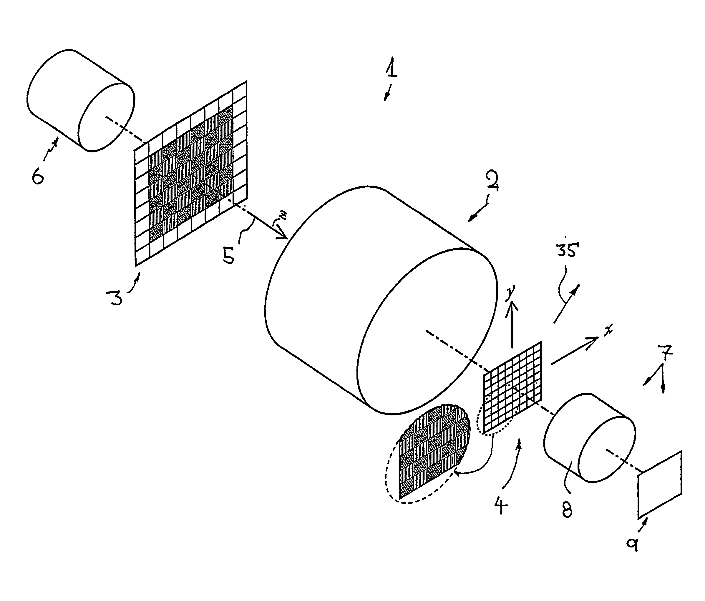
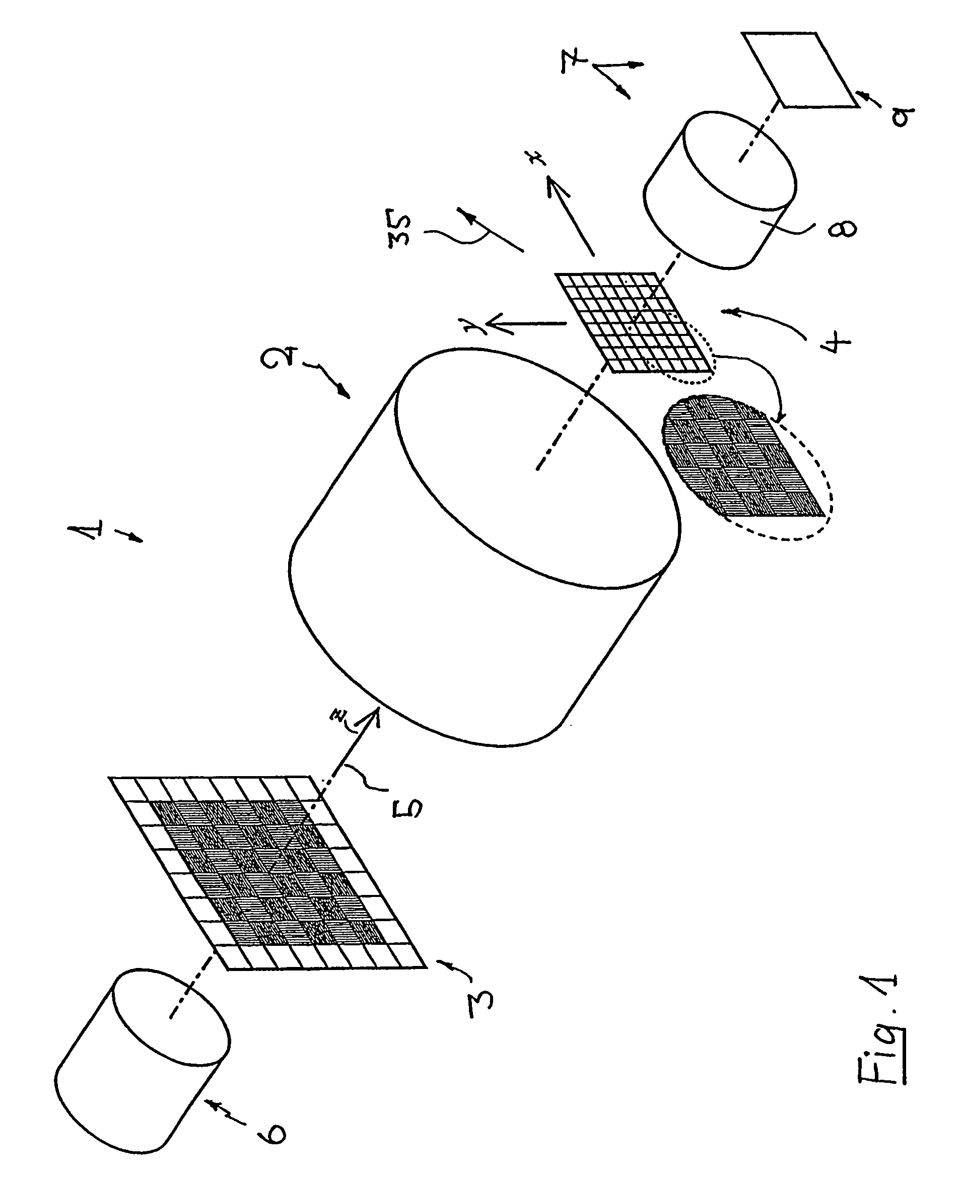
[0057]The invention is explained below with the aid of distortion measurement in the case of a microlithographic projection objective, but can also be used to measure other optical imaging systems, for example photographic objectives or the like, and to measure other imaging properties, for example contrast, astigmatism, image shape etc.

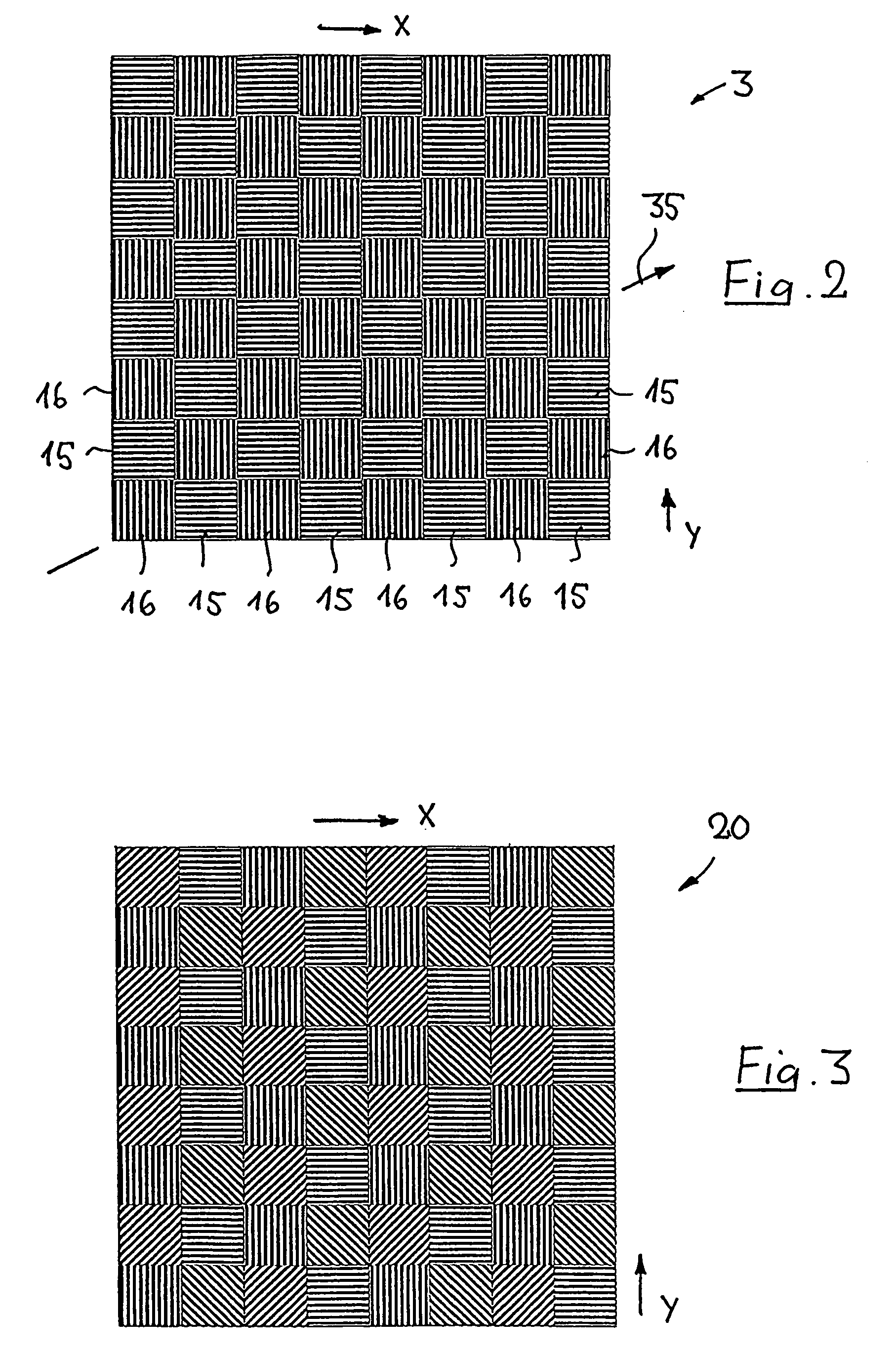
[0058]The distortion measuring system 1, shown in FIG. 1, for measuring the distortion of a projection objective 2 comprises an object grating 3, arranged in the object plane of a projection objective 2, and an image grating 4 arranged in the image plane of the projection objective that is conjugate with the object plane. The transmission gratings 3 and 4 are each arranged perpendicular to the optical axis 5 of the measuring system (z-axis), which is to be aligned parallel to the optical axis of the objective 2 and coincides in the example shown with this optical axis. The image grating 4 is held displaceably in the x-y plane lying perpendicular to t...


PUM

PropertyMeasurementUnit
angleaaaaaaaaaa
angleaaaaaaaaaa
relative displacementaaaaaaaaaa

Abstract

In the case of a method and a measuring system for measuring the distortion of an optical imaging system with the aid of moiré patterns, an object grating with an object pattern is arranged in the object plane of the imaging system, and an image grating with an image pattern is arranged in the image plane of the imaging system. Both the object pattern and the image pattern in each case have a multiplicity of cells with sub-gratings of different grating properties, it being possible, in particular, for the sub-gratings to have different directions of periodicity and different phase angles. The object pattern and the image pattern are coordinated with one another in such a way that, when the object pattern is projected onto the image pattern with the aid of the imaging system, images of the sub-gratings of the object pattern superimpose in each case with assigned sub-gratings of the image pattern, accompanied by the generation of moiré sub-patterns, which are likewise present in the form of cells situated next to one another. As a result, it is possible simultaneously to determine distortion components for a plurality of image directions aligned transverse to one another. It is preferred to use phase-shift methods in order to evaluate the moiré sub-pattern.

Description

[0001]The present application is a Continuation of International Application PCT / EP03 / 02283, with an international filing date of Mar. 6, 2003, which was published under PCT Article 21(2) in English, and the disclosure of which is incorporated into this application by reference; the present application further claims priority to U.S. Provisional Application No. 60 / 362,552, filed on Mar. 8, 2002.BACKGROUND OF THE INVENTION[0002]1. Field of the Invention[0003]The invention relates to a moiré method for measuring aberrations, particularly the distortion of an optical imaging system, and to a measuring system suitable for carrying out the method.[0004]2. Description of the Related Art[0005]In many fields of technology and research, use is made of optical imaging systems on which ever higher demands are being places as regards imaging quality. An example is the photolithographic production of semiconductor components and other finely structured components in the case of which structures ...

Claims


Application Information

Patent Timeline
Patent Type & Authority Patents(United States)
IPC IPC(8): G01B9/00G01B11/14G01M11/02G01M11/00G03F7/20H01L21/027
CPCG03F7/706
Inventor WEGMANN, ULRICHSCHELLHORN, UWEKLAESGES, RALPHSTUEHLER, JOACHIM
Owner CARL ZEISS SMT GMBH
Why Eureka
Try Eureka