
Microfluidic system including a virtual wall fluid interface port for interfacing fluids with the microfluidic system

a microfluidic system and fluid interface technology, applied in the field of fluid interface ports, can solve the problems of limited processing capacity of microfluidic systems, process that is also diffusion limited, and limited the number of samples and other fluids that can be processed on a microfluidic substrate, and achieve the effect of suitable cross sectional dimensions

Inactive Publication Date: 2007-05-01
CYTONOMEST
View PDF57 Cites 70 Cited by
  • Summary
  • Abstract
  • Description
  • Claims
  • Application Information

AI Technical Summary

Benefits of technology

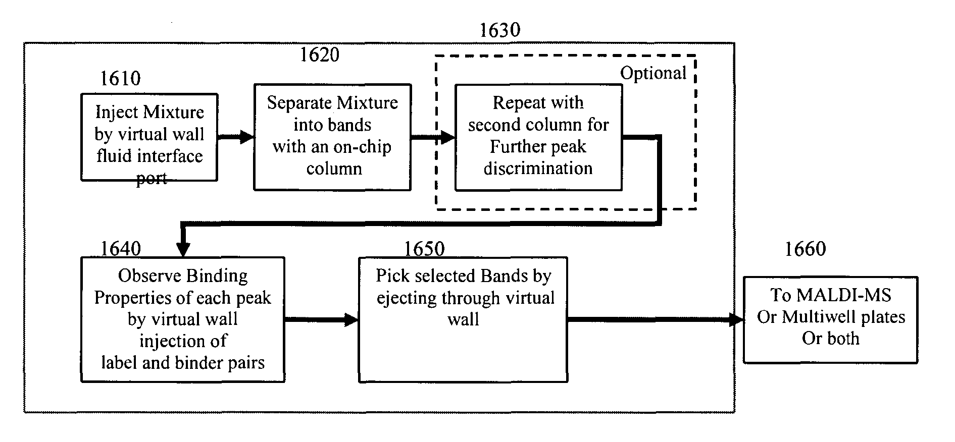
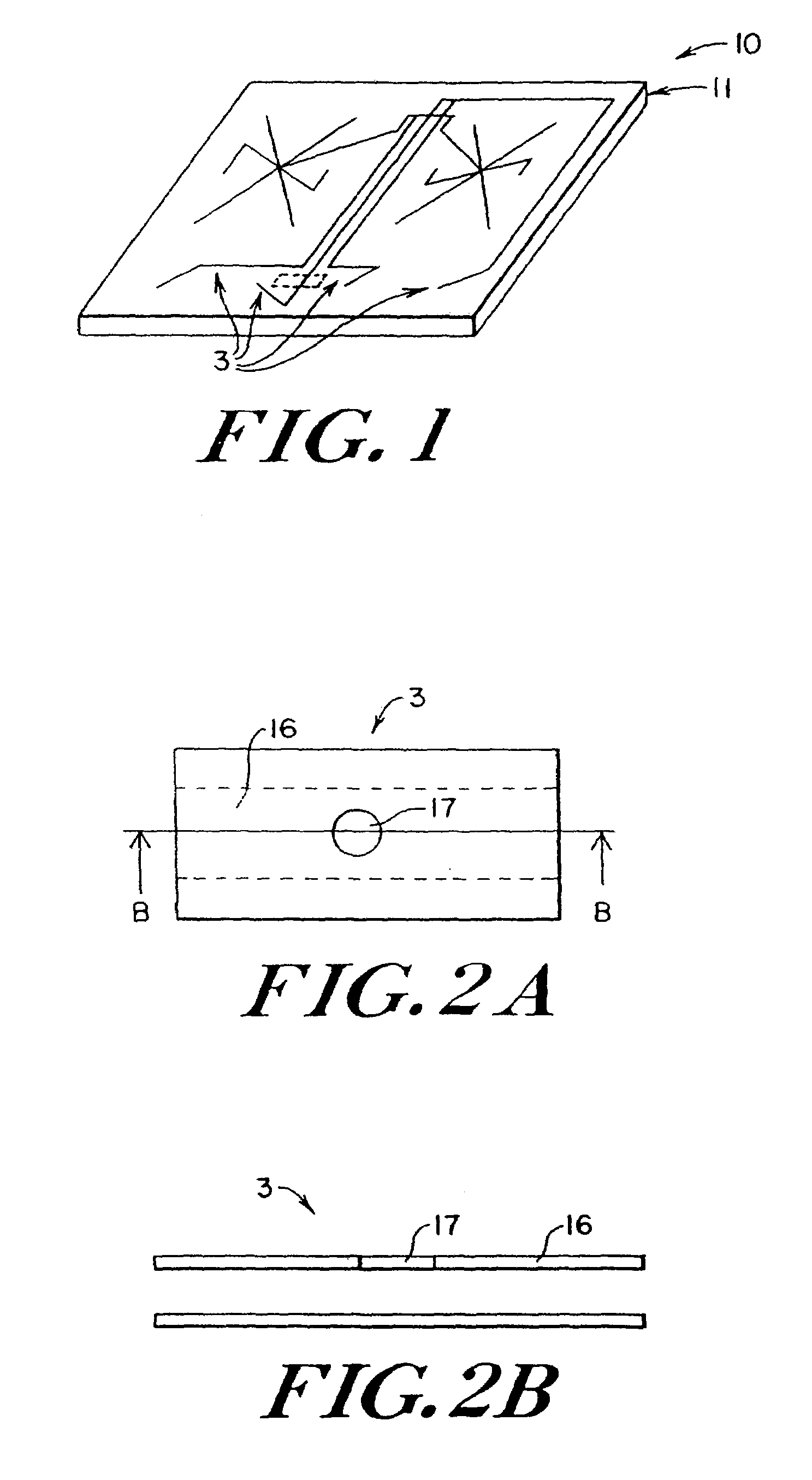
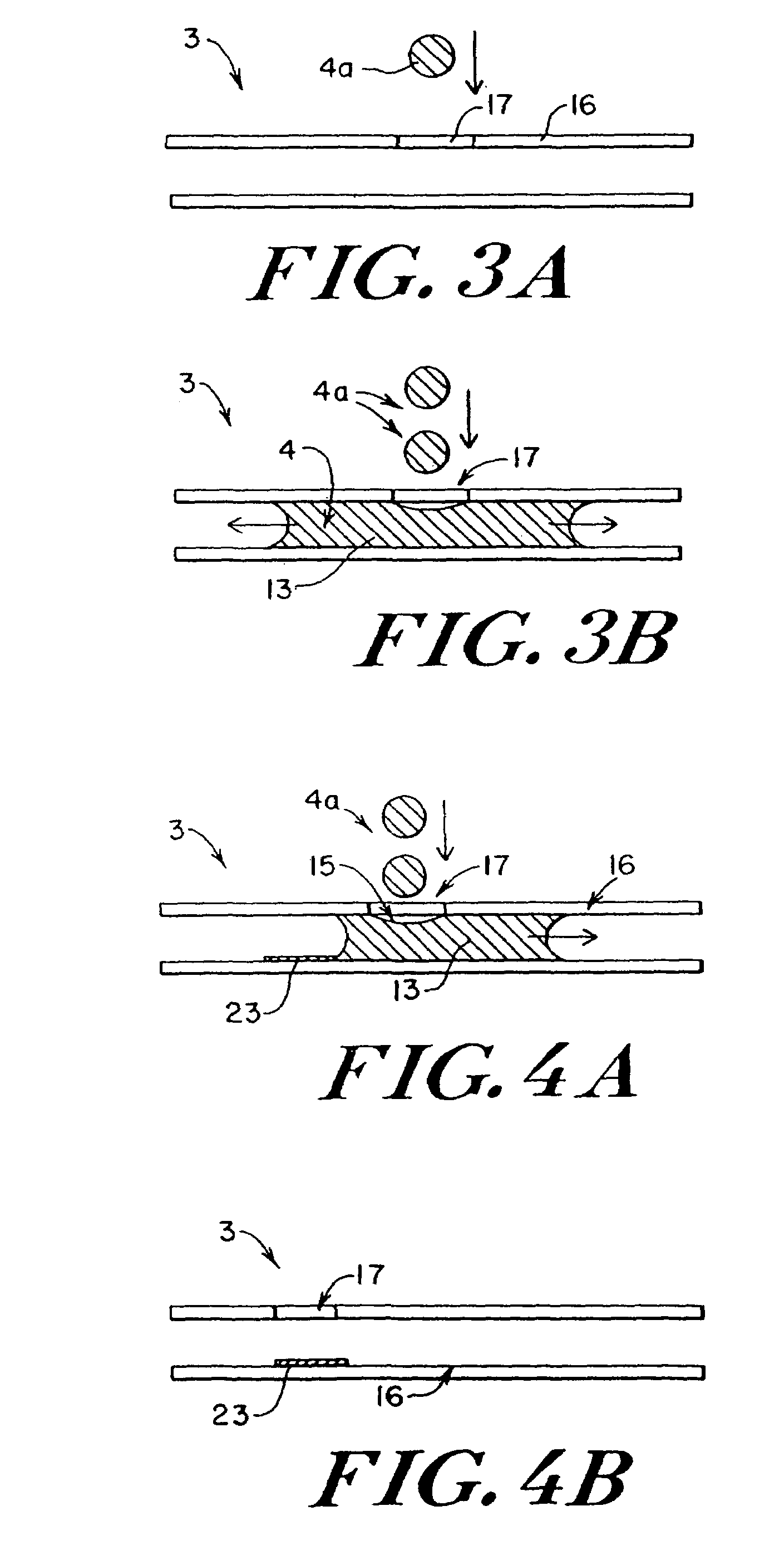
The present invention provides methods, devices, and systems for interfacing fluids in microfluidic systems. The invention includes a microchannel with an opening in its sidewall that acts as a virtual wall, allowing fluids to be directly interfaced without affecting fluid flow. The virtual wall can be used for introducing and ejecting fluids, as well as for performing labeling operations on samples. The technical effects of the invention include fast transient measurement of unlabeled molecules based on their binding affinity and detection of molecules based on their binding affinity. The system can also include a separation region for separating samples and a first fluid interface port for injecting labeling molecules into the system.

Problems solved by technology

Another example of the efficiency of microfluidic systems is the mixing of dissolved species in a liquid, a process that is also diffusion limited.
In conventional microfluidic systems, the structures and methods used to introduce samples and other fluids into microfluidic substrates limit the capabilities of the microfluidic systems.
The total number of samples and other fluids that can be processed on a microfluidic substrate is currently limited by the size and / or the number of reservoirs through which these fluids are introduced to the microfluidic system.
A disadvantage of known structures and methods for introducing fluids into a microfluidic system is the use and transfer of a much greater volume of fluid than is needed for microfluidic analysis due to significant size inefficiencies and sample loss.
Furthermore, with conventional methods of introducing fluids into microfluidic systems, it is difficult to control the amount of sample introduces that is eventually introduces into the microchannel after passing through a sample channel or a reservoir.
A major disadvantage of this approach for fluidic interfacing is the complex construction and operation of these micropumps and valves.
Another disadvantage is there relatively large size and internal volume when compared to the internal volume of the microchannels.
Often there are multiple orders of magnitude between these two volumes and the resulting discrepancy renders micropumps unattractive to interface with a large number of small dimensional microchannels.
The size of the device does not allow the interfacing with a large number of microchannels, and between consecutive injections, the device needs to be cleaned, thereby considerably reducing throughput.
A disadvantage is that the precise amount of injected liquids and substances depends upon a large number of factors which are difficult to control.
It is also a disadvantage that it does not allow the efficient interfacing with a large number of different liquids as for every injection port, a separate high voltage supply is required, together with the associated liquid channels for providing a closed electrical circuit.
A disadvantage is that only a very small fraction of the applied liquid is actually introduced in the target microchannel, the bulk of the applied liquid drop remains behind in the well by capillary forces.
As a result, most of the liquid is wasted and is not available for a consecutive chemical processing step.
A low injection efficiency is disadvantageous because it indicates inefficient use of chemical substances and an increased production of waste.
Besides the complexity of the required fluidic manifolds and pressurizing system, also here a disadvantage is the inherently low injection efficiency as only a very small fraction of the applied liquid is actually used in the experiment.
One disadvantage is that if a large number of liquids need to be handled, for instance in high-throughput synthesis and screening applications, a large number of wells need to be integrated on the microfluidic device.
As the costs of microfluidic chips strongly depends on the chip surface, the required integration of wells renders this liquid injection scheme unattractive for high-throughput synthesis and screening applications.
Another disadvantage of conventional systems is that for every well, a separate electrode is required together with electronic circuitry for the application of the driving voltages.
This requirement results in a complex and expensive apparatus.
Another specific disadvantage with electrokinetic injection is the fact that during the application of the driving voltage on the electrode the electrolysis of water results in the generation of hydroxyl ions (OH−), hydrogen ions (H+), hydrogen gas (H2) and oxygen gas (O2).
The generated ions will affect the acidity (i.e. pH) of the liquid pumped from the first well, whilst the produced gasses potentially give rise to the formation of gas bubbles in the microfluidic system thereby destroying the experiment and eventually the microfluidic device.
For instance, the presence of chloride ions, an ion present in most liquid media, will result in the formation of chlorine gas, which on turn can interact and potentially destroy vulnerable (biochemical) compounds present in the liquid to be injected.
Another disadvantage of electrokinetic injection is that in between consecutive experiments, the well need to be thoroughly cleaned in order to prevent cross-contamination.
This required cleaning step results in a reduction of throughput and makes it difficult to implement on-line monitoring.
Another disadvantage is that the liquid to be injected is subjected to a high voltage.
This aspect of the absence of galvanic separation makes it virtually impossible to use electrokinetic injection for in-vivo or near-vivo applications due to the danger of electrocution.
Another disadvantage is that the electrokinetic injection methods referred to, are only applicable in chip like systems produced via microfabrication technology, i.e. via the use of expensive equipment and processes also applied for the fabrication of computer chips.
These methods are known to have high costs.
Still another disadvantage is the low injection efficiency of electrokinetic injection.
A disadvantage of this fluidic interfacing method is that for a correct and efficient operation the pressure generating air chamber together with electronic heater components need to be integrated with the microfluidic system.
This results in a complex device with associated large costs.
It can be concluded based on the above that current methods and systems for fluidic interfacing with microfluidic devices have particular disadvantages regarding the difficulty of integration of a large number of chemical operation nodes to interface with (i.e. electrochromatography columns, reactors etc.), relatively large required liquid volumes, low injection efficiency, electrochemical sample pollution, long rinse time between analysis steps, galvanic separation and required microfabrication technologies.
Besides these disadvantages, none of the above mentioned interfacing methods allow bi-directional fluidic interfacing, i.e. transporting liquids to and from microfluidic systems.

Method used


Image

  • Microfluidic system including a virtual wall fluid interface port for interfacing fluids with the microfluidic system
  • Microfluidic system including a virtual wall fluid interface port for interfacing fluids with the microfluidic system
  • Microfluidic system including a virtual wall fluid interface port for interfacing fluids with the microfluidic system

Examples


example 1

Virtual Wall Microfluidic Chip Manufacturing and Use

[0182]Microchannel structures having a fluid interface port were manufactured by isotropic etching half-open channels, 100 micrometer in width, 50 micrometer in height and a length of 20 mm, in a 1.1 mm thick glass wafer. A buffered hydrogen fluoride (HF) solution was used as an etchant and photo patterned etchant resistant silicon nitride mask layers were applied to define the microchannel areas to be etched. Access to the channels was provided by powder blasting 1-mm diameter holes completely through the glass wafer at both ends of each etched half-open microchannel.

[0183]A covering 50 micrometer thick layer of dry resist film (LAMINAR® 5000, Shipley, Birkenfeld, Germany) was applied on top of the etched wafer. Fluid interface ports were incorporated by photo patterning circular apertures of 50–150 micrometer in the dry resist film whereby the apertures were aligned with and extended into the underlying microchannels. Finally the...


PUM

PropertyMeasurementUnit
diameteraaaaaaaaaa
diameteraaaaaaaaaa
diameteraaaaaaaaaa

Abstract

A fluid interface port in a microfluidic system and a method of forming the fluid interface port is provided. The fluid interface port comprises an opening formed in the side wall of a microchannel sized and dimensioned to form a virtual wall when the microchannel is filled with a first liquid. The fluid interface port is utilized to perform a labeling operation on a sample.

Description

RELATED APPLICATIONS[0001]The present application is a continuation-in-part of U.S. patent application Ser. No. 10 / 028,852, filed Dec. 21, 2001 and entitled Microfluidic System Including a Virtual Wall Fluid Interface Port for Interfacing Fluids With the Microfluidic System, the contents of which are herein incorporated by reference. The present application also claims priority to U.S. Provisional Patent Application Ser. No. 60 / 391,872, filed Jun. 25, 2002 and entitled Microfluidic Chip with Post-Column Labeling, the contents of which are herein incorporated by reference.FIELD OF THE INVENTION[0002]The present invention relates to fluidic interface ports for providing bi-directional fluid interfacing in a microfluidic system. More specifically, the present invention relates to the use of a fluidic interface port in a microfluidic system for performing a labeling operation.BACKGROUND OF THE INVENTION[0003]In the chemical, biomedical, bioscience and pharmaceutical industries, it has b...

Claims


Application Information

Patent Timeline
Patent Type & Authority Patents(United States)
IPC IPC(8): G01N1/18G01N1/10G01N15/06G01N33/566G01N35/00B01L3/02C12Q1/00G01N27/447G01N35/10
CPCB01D57/02B01F13/0071B01J19/0093B01L3/0244B01L3/0268B01L3/502715B01L3/502792C12Q1/00G01N27/44743G01N27/44782G01N27/44791B01F13/0059Y10T436/118339B01J2219/00371B01J2219/00378B01J2219/00783B01J2219/00831B01J2219/00837B01J2219/00869B01J2219/00889B01J2219/00891B01J2219/00905B01L2200/027B01L2200/143B01L2200/147B01L2300/087B01L2300/089B01L2400/0406B01L2400/0415B01L2400/0421B01L2400/0439B01L2400/0487G01N27/447G01N2035/1037Y10T436/25375Y10T436/25Y10T436/11Y10T436/2575Y10T436/117497Y10T436/13B01F33/3021B01F33/30
Inventor GILBERT, JOHN R.CHIEM, NGHIA HUNG
Owner CYTONOMEST
Learn More