Method and apparatus for optical sensing

a technology of optical sensing and optical sensing equipment, applied in the field of optical sensing, can solve the problems of limiting the strain measurement, slow scanning rate, and limited strain resolution, and achieve the effect of fast quantitative measuremen

Active Publication Date: 2012-03-15
SILIXA
View PDF34 Cites 69 Cited by
  • Summary
  • Abstract
  • Description
  • Claims
  • Application Information

AI Technical Summary

Benefits of technology

[0012]The present invention provides novel apparatus and methods for fast quantitative measurement of perturbation of optical fields transmitted, reflected and or scattered along a length of an optical fibre.

Problems solved by technology

However, due to their slow response, distributed sensors are usually only used in applications where measurements taking in order of several seconds to hours are acceptable.
However, using these approaches, the scanning rate is much slower than the pulse repetition rate and measurement times are typically in the order of few seconds to few minutes.
However, the strain resolution is limited by the linewidth of the Brillouin light and therefore the optical path length difference in the interferometer should be kept within the coherence length of the Brillouin light.
Also, the polarisation fading between the two paths of the interferometer, the offset and gain variations of the photodetector receivers would significantly limit the strain measurement.
However, unlike with distributed sensors, multiplexed point sensors cannot be used where full coverage is required.
Furthermore, the sensor design relies on additional optical fibre components leading to bulky and expensive array architectures.
There is also considerable effort to increase the number of sensors that can be efficiently multiplexed on a single length of fibre.
However, this requires matching of the laser wavelength with the narrow band optical filter, which results in the signal visibility variation being reduced compared to a system which uses a very high coherent source as proposed by U.S. Pat. No. 5,194,847.
However, the response of these coherent Rayleigh backscatter systems has been limited by a number of parameters such as polarisation and signal fading phenomena; the random variation of the backscatter light; and non-linear coherent Rayleigh response.
Therefore these techniques are mainly used for event detection and do not provide quantitative measurements, such as the measurement of acoustic amplitude, frequency and phase over a wide range of frequency and dynamic range.

Method used


Image

  • Method and apparatus for optical sensing
  • Method and apparatus for optical sensing
  • Method and apparatus for optical sensing

Examples


first embodiment

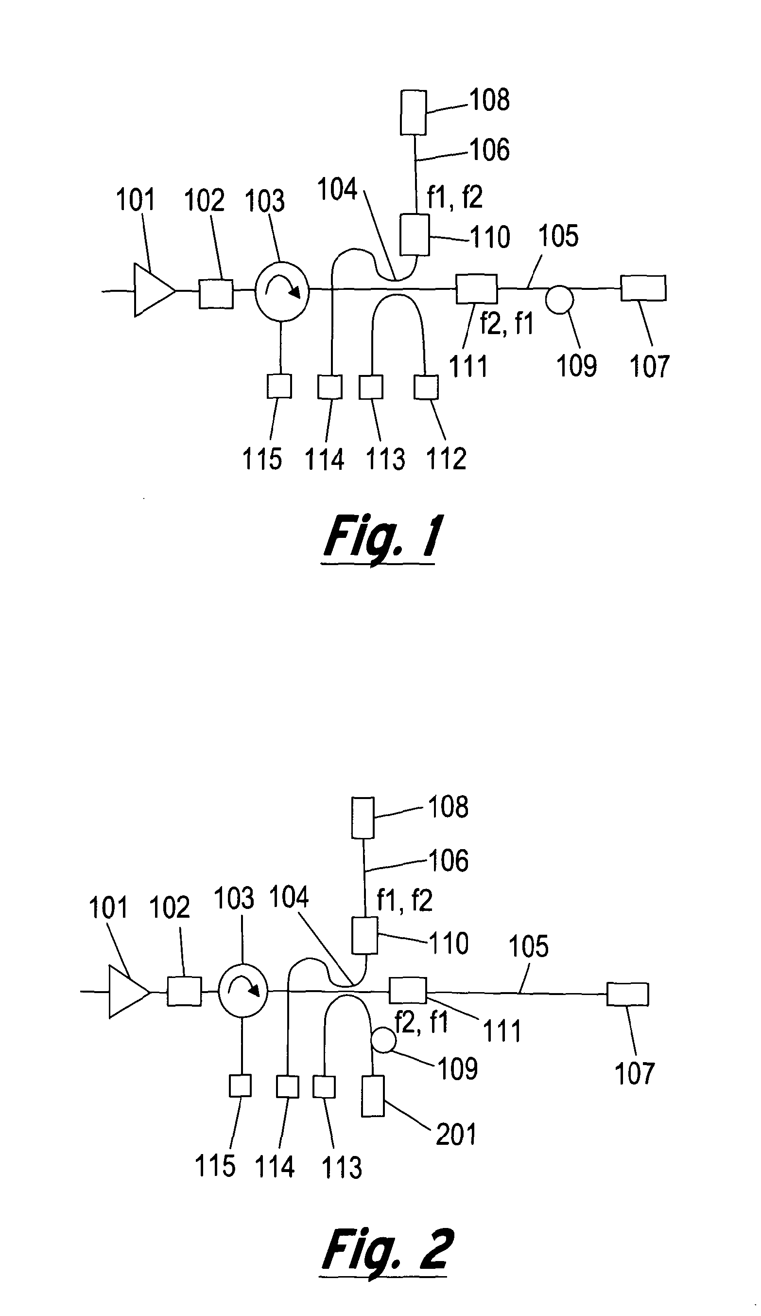
[0032]FIG. 1 shows a first embodiment, generally depicted at 100, of a novel interferometer for measuring the optical amplitude, phase and frequency of an optical signal. The incoming light from a light source (not shown) is preferably amplified in an optical amplifier 101, and transmitted to the optical filter 102. The filter 102 filters the out of band Amplified Spontaneous Emission noise (ASE) of the amplifier 101. The light then enters into an optical circulator 103 which is connected to a 3×3 optical coupler 104. A portion of the light is directed to the photodetector 112 to monitor the light intensity of the input light. The other portions of light are directed along first and second optical paths 105 and 106, with a path length difference between the two paths. Faraday-rotator mirrors (FRMs) 107 and 108 reflect the light back through the first and second paths 105 and 106, respectively. The Faraday rotator mirrors provide self-polarisation compensation along optical paths 105...

embodiment 700

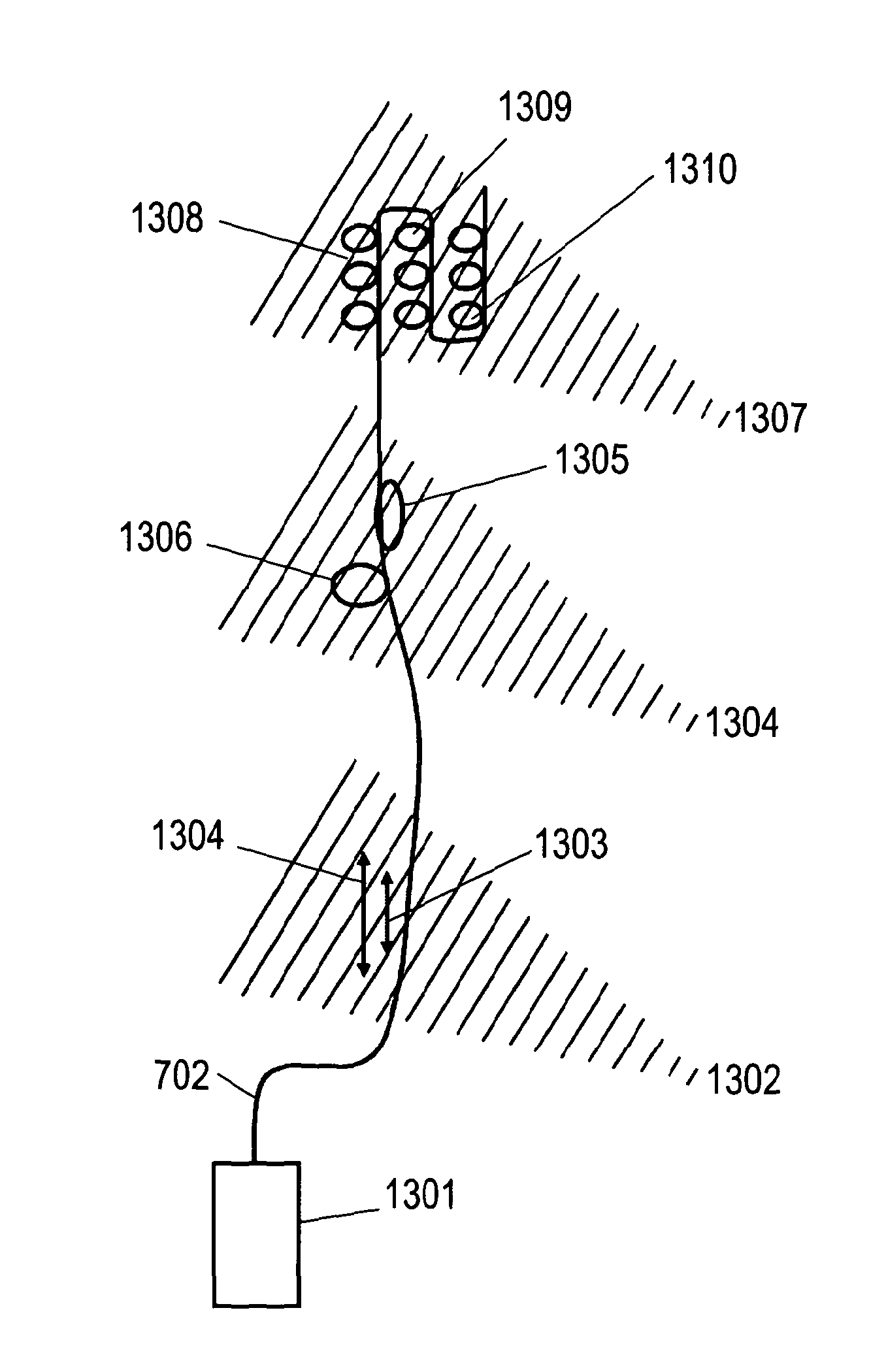
[0039]In this embodiment 700, light emitted by a laser 701 is modulated by a pulse signal 702. An optical amplifier 705 is used to boost the pulsed laser light, and this is followed by a band-pass filter 706 to filter out the ASE noise of the amplifier. The optical signal is then sent to an optical circulator 707. An additional optical filter 708 may be used at one port of the circulator 707. The light is sent to sensing fibre 712, which is for example a single mode fibre or a multimode fibre deployed in an environment in which acoustic perturbations are desired to be monitored. A length of the fibre may be isolated and used as a reference section 710, for example in a “quiet” location. The reference section 710 may be formed between reflectors or a combination of beam splitters and reflectors 709 and 711.

[0040]The reflected and the backscattered light generated along the sensing fibre 712 is directed through the circulator 707 and into the interferometer 713. The detailed operation...


PUM


Abstract

The present invention provides novel apparatus and methods for fast quantitative measurement of perturbation of optical fields transmitted, reflected and/or scattered along a length of an optical fibre. The present invention can be used for point sensors as well as distributed sensors or the combination of both. In particular this technique can be applied to distributed sensors while extending dramatically the speed and sensitivity to allow the detection of acoustic perturbations anywhere along a length of an optical fibre while achieving fine spatial resolution. The present invention offers unique advantages in a broad range of acoustic sensing and imaging applications. Typical uses are for monitoring oil and gas wells such as for distributed flow metering and/or imaging, seismic imaging, monitoring long cables and pipelines, imaging within large vessel as well as for security applications.

Description

FIELD OF THE INVENTION[0001]The present invention relates to optical sensors and, in particular, distributed optical fibre sensors and applications thereof.BACKGROUND TO THE INVENTION[0002]The benefits of optical fibres have been demonstrated in a number of sensing applications. The two major areas are: (i) distributed optical fibre sensors, and (ii) multiplexed point sensor arrays.[0003]Distributed sensors utilise the intensity of backscatter light, with Raman and / or Brillouin peaks in the light signal utilised to measure temperature, strain or pressure. Distributed sensors offer a number of advantages including continuous sensing along the entire length of fibre, and flexibility and simplicity of the sensor, which may be standard telecoms optical fibre. For example, a distributed sensor may provide 10,000 measurement points along 10 km of optical fibre with a 1 m spatial resolution. Distributed sensor systems therefore offer low installation and ownership costs.[0004]However, due ...

Claims


Application Information

Patent Timeline
Patent Type & Authority Applications(United States)
IPC IPC(8): G01H9/00G01D5/353
CPCG01D5/35303G01D5/35325G01D5/35358G01M5/0091G01M5/0058G01M11/085G01V1/226G01H9/004G01V1/40G01M3/24G01M5/0066G01F1/666G01F1/661G01F1/662G01F1/667G01D5/353G01S5/30G01V1/38G01D5/35306G01D5/35374G01J9/02G08B13/186F16L55/48G01F1/7086G01D5/35354G01B9/02003G01V1/187G01B9/02G01D5/268E21B47/135G01D5/35383G01D5/35364E21B47/002E21B47/107E21B47/0025G01D5/35335G01M11/331G01F1/66G01D5/35377
Inventor FARHADIROUSHAN, MAHMOUDPARKER, TOM RICHARDSHATALIN, SERGEY
Owner SILIXA
Why Eureka
Try Eureka