Display device and video viewing system

a display device and video technology, applied in the field of display devices and video viewing systems, can solve the problems of difficult for the viewer to stereoscopically perceive the frame images displayed, and the problem of crosstalk is a common problem in two-dimensional, and achieve the effect of suppressing crosstalk

Active Publication Date: 2012-06-28
PANASONIC INTELLECTUAL PROPERTY CORP OF AMERICA
View PDF10 Cites 14 Cited by
  • Summary
  • Abstract
  • Description
  • Claims
  • Application Information

AI Technical Summary

Benefits of technology

[0020]The display device and the video viewing system according to the present invention may suppress the crosstalk.

Problems solved by technology

Therefore, it is difficult for the viewer to stereoscopically perceive the frame images displayed at the lower portion of the liquid crystal panel 904.
The aforementioned crosstalk problem becomes noticeable, in particular, in stereoscopic video display in which the L and R frame images rendering different contents from each other by the parallax amount are alternately displayed, although the crosstalk problem is a common problem to two-dimensional videos.

Method used


Image

  • Display device and video viewing system
  • Display device and video viewing system
  • Display device and video viewing system

Examples


first embodiment

Configuration of Video Viewing System

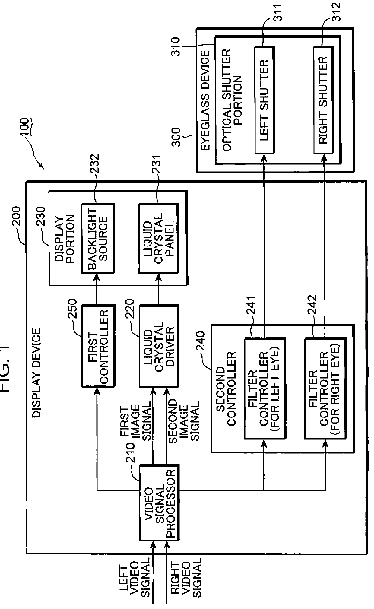
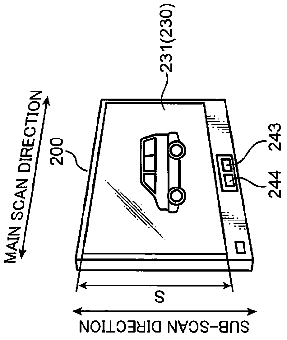
[0058]FIG. 1 is a schematic block diagram showing the configuration of a video viewing system according to the first embodiment. FIG. 2 is a schematic view showing the video viewing system depicted in FIG. 1. A schematic configuration of the video viewing system is described with reference to FIGS. 1 and 2.

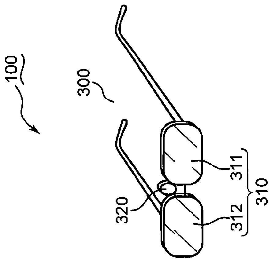
[0059]A video viewing system 100 has a display device 200 and an eyeglass device 300. The display device 200 displays frame images including left frame images (hereinafter, referred to as L frame images), which are viewed by the left eye, and right frame images (hereinafter, referred to as R frame images), which are viewed by the right eye. The eyeglass device 300 assists in viewing the L and R frame images which the display device 200 displays. The eyeglass device 300 performs a stereovision assistance which is in sync with the L and R frame images that the display device 200 displays, so that a viewer views the L and R frame images by the lef...

second embodiment

[0196]FIG. 22 is a schematic block diagram of a video signal processor used in a video viewing system and a display device according to the second embodiment. Components other than the video signal processor are the same as the components described in the context of the first embodiment. The same reference symbols are assigned to the identical components to the first embodiment. The descriptions in the context of the first embodiment are appropriately applied to components which are not described below. The video signal processor used in the video viewing system and the display device according to the second embodiment is described with reference to FIGS. 13 and 22.

[0197]The video signal processor 210A used in the video viewing system and the display device according to the second embodiment includes a third equalizer 251 and a fourth equalizer 252, in addition to the first equalizer 211, the first selector 212, the first delay portion 213, the second equalizer 214, the first correc...

third embodiment

[0210]In the third embodiment, control in response to a display area of a frame image is described.

[0211]FIG. 25 is a schematic timing chart showing changes in luminance of pixels when the second corrector 218 outputs equivalent second correction values for an upper portion and a lower portion of a frame image. Resultant problems from the equivalent second correction values used for the upper and lower portions of the frame image are described with reference to FIGS. 1, 5A, 5B, 15 and 25.

[0212]The left period for displaying the N-th L frame image, the right period for displaying the N-th R frame image and the left period for displaying the (N+1)-th L frame image are shown in the section (A) of FIG. 25. Changes in luminance of pixels in the right period are described.

[0213]The section (B) of FIG. 25 shows the first and second scanning operations. The second scanning period during which the second scanning operation is performed is longer than the first scanning period during which th...


PUM


Abstract

A display device includes: a liquid crystal panel including a display surface on which frame images are displayed; a conversion portion for converting a frame image signal into a first image signal representing an image having a lower resolution and a second image signal representing an image having a higher resolution; and a liquid crystal driver for driving the liquid crystal panel with performing first and second scanning operations of the first and second image signals over pixels of the entire display surface. The liquid crystal driver performs the second scanning operation with targeting a drive luminance value which is set in response to an expected value of an achieved luminance value during the first scanning operation for the pixel of the display surface before the second scanning operation commences, and target luminance value for the pixels defined by the frame image signal.

Description

TECHNICAL FIELD[0001]The present invention is related to a display device and a video viewing system which display videos.BACKGROUND OF THE INVENTION[0002]A display device which makes a displayed video stereoscopically perceived alternately displays a left frame image (referred to as L frame image hereinafter) which is viewed by the left eye and a right frame image (referred to as R frame image hereinafter) which is viewed by the right eye, at predetermined intervals (e.g., field intervals). The displayed L and R frame images have contents different from each other by an amount of parallax. A viewer views the L and R frame images through an eyeglass device which has liquid crystal shutters driven in sync with display periods of the L and R frame images (c.f., JP S62-133891 A and JP 2009-25436 A). Thus, the viewer stereoscopically perceives objects rendered in the L and R frame images.[0003]FIG. 32 is a block diagram showing a conventional video viewing system. The video viewing syst...

Claims


Application Information

Patent Timeline
Patent Type & Authority Applications(United States)
IPC IPC(8): G09G5/10H04N13/04G06T15/00
CPCH04N13/0438H04N13/0018H04N13/122H04N13/341
Inventor KOBAYASHI, TAKAHIROUMEDA, YOSHIO
Owner PANASONIC INTELLECTUAL PROPERTY CORP OF AMERICA
Why Eureka
Try Eureka