
Crank type valve driving device

A driving device and crank-type technology, which is applied in the field of valve manufacturing, can solve the problems of uncontrollable opening and closing angles, excessive adjustment, and inability to adjust opening and closing. Effect

Inactive Publication Date: 2011-11-02
YANGZHOU XIBOSI TECH DEV
View PDF0 Cites 1 Cited by
  • Summary
  • Abstract
  • Description
  • Claims
  • Application Information

AI Technical Summary

Problems solved by technology

[0003] The invention provides a bellcrank type valve driving device, which aims to solve the defects that the opening and closing of the existing bellows type valve cannot be adjusted, the opening and closing angles cannot be controlled, and the over-adjustment is prone to occur.

Method used


Image

  • Crank type valve driving device
  • Crank type valve driving device
  • Crank type valve driving device

Examples


Embodiment Construction

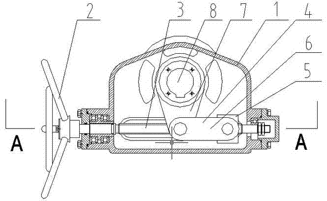
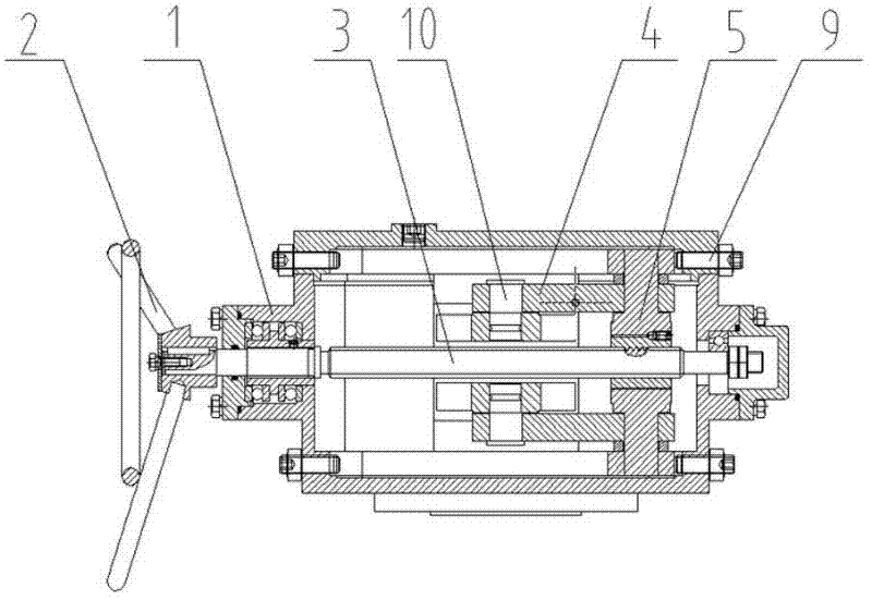
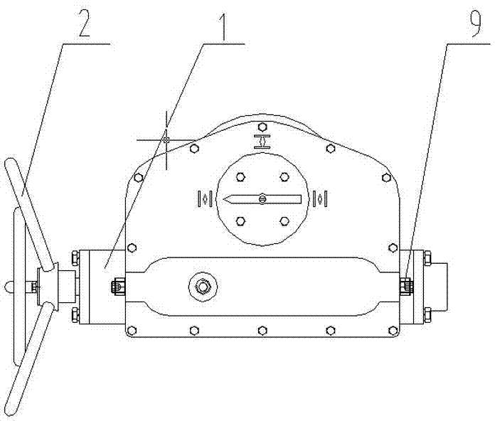
[0011] Such as figure 1 , 2 As shown, the bellcrank type valve driving device includes a box body 1, a hand wheel assembly 2, a screw rod 3, a swing arm 4, and a valve rod 8. Both ends of the screw rod 3 are respectively connected to the box body 1 through bearings, and the hand The wheel assembly 2 is fixedly connected to the left end of the screw mandrel 3, and the nut sleeve 5 is threaded on the screw mandrel 3; the swing arm 4 includes a first swing arm 6 and a second swing arm 7, and the first swing arm 6 is fixedly connected to the nut sleeve 5 Above, the first swing arm 6 is parallel to the screw rod 3, one end of the second swing arm 7 is hinged to the left end of the first swing arm 6 through a support pin 10, and the other end of the second swing arm 7 is fixedly connected to the swing arm 4 and is perpendicular to The valve stem 8 is provided with mechanical stop bolts 9 at the left and right ends of the upper part of the box body 1 respectively. Set the mechanica...


PUM


Abstract

The invention relates to a crank type valve driving device, belonging to the technical field of valve manufacturing. The crank type valve driving device comprises a box body, a hand wheel assembly, a screw rod, swing arms and a valve rod, wherein both ends of the screw rod are respectively connected to the box body through bearings, the hand wheel assembly is fixedly connected at the left end of the screw rod, and a nut sleeve is in thread connection to the screw rod; the swing arms comprise a first swing arm and a second swing arm, the swing arm is fixedly connected on the nut sleeve, and the first arm and the screw rod are parallel; one end of the second swing arm is hinged at the left end of the first swing arm through a backing pin, and the other end of the second swing arm is fixedly connected with the valve rod perpendicular to the swing arm; and the left end and the right end of the upper part of the box body are respectively provided with a mechanical limiting bolt, and the mechanical limiting bolts and the first swing arm are arranged on the same plane. The device controls the stroke of the adjusting nut sleeve and the swing arms by adjusting the length of the mechanical limiting bolts stretching into the box body, and a valve switch is avoided from going beyond the limit to control the opening and closing angle of the valve.

Description

technical field [0001] The invention relates to the technical field of valve manufacture. Background technique [0002] The existing bellcrank valve includes a box body, a hand wheel assembly, a screw rod, a swing arm, and a valve rod. The left and right ends of the body, the said swing arm includes a first swing arm and a second swing arm at the threaded screw connection nut sleeve, the first swing arm is fixedly connected to the nut sleeve, the first swing arm The arm is parallel to the screw rod, one end of the second swing arm is hinged to the left end of the first swing arm through a support pin, and the other end of the second swing arm is fixedly connected to the valve stem perpendicular to the swing arm; existing The opening and closing of the crank-type valve cannot be adjusted, and the opening and closing angle cannot be controlled, and it is easy to over-adjust. Contents of the invention [0003] The invention provides a bellcrank type valve driving device, ai...

Claims


Application Information

Patent Timeline
Patent Type & Authority Applications(China)
IPC IPC(8): F16K31/60F16K31/50
Inventor 董侠均
Owner YANGZHOU XIBOSI TECH DEV
Learn More