Basin covering device

A technology of parts and small casters, which is applied in the field of entertainment pools, can solve the problems that have not been raised, and achieve the effect of reducing the volume and increasing the stacking volume

Inactive Publication Date: 2011-11-23
ABRISUD
View PDF7 Cites 2 Cited by
  • Summary
  • Abstract
  • Description
  • Claims
  • Application Information

AI Technical Summary

Problems solved by technology

[0010] Thus, neither of the arrangements described in these two references proposes any means to reduce the volume excessively occupied by the covering or roof elements in the stacked position due to the presence of the runners

Method used


Image

  • Basin covering device
  • Basin covering device
  • Basin covering device

Examples


Embodiment Construction

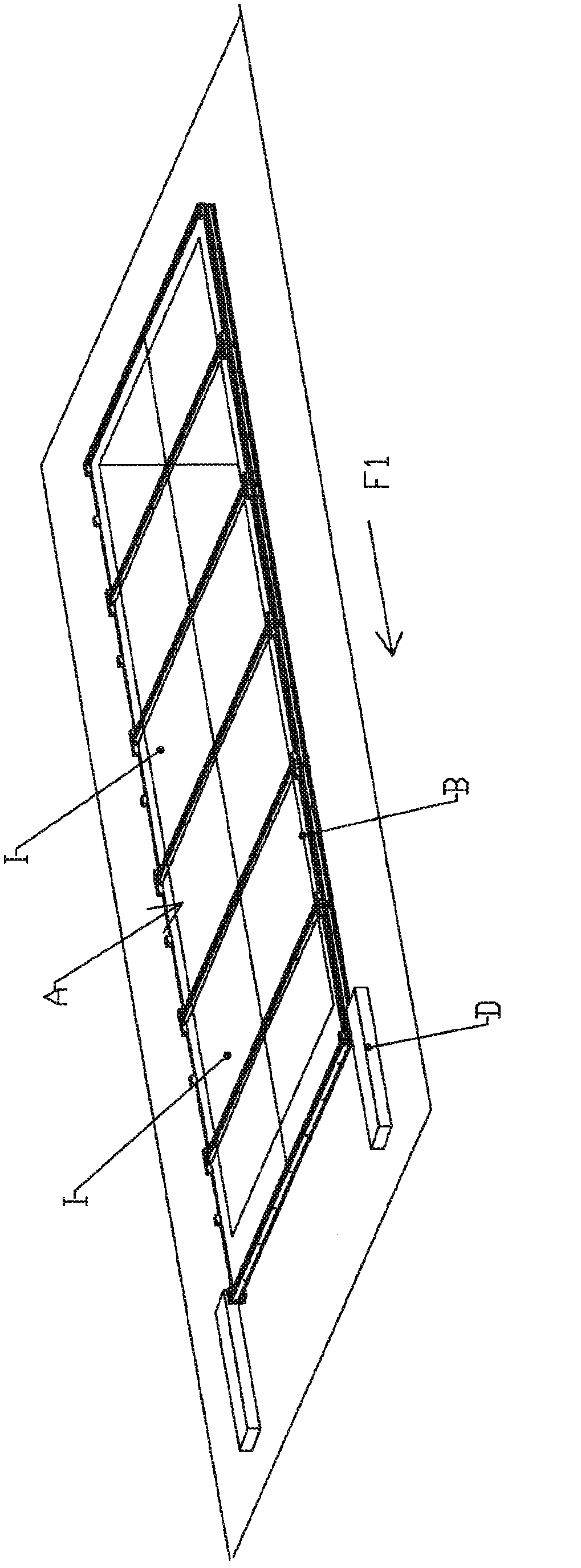
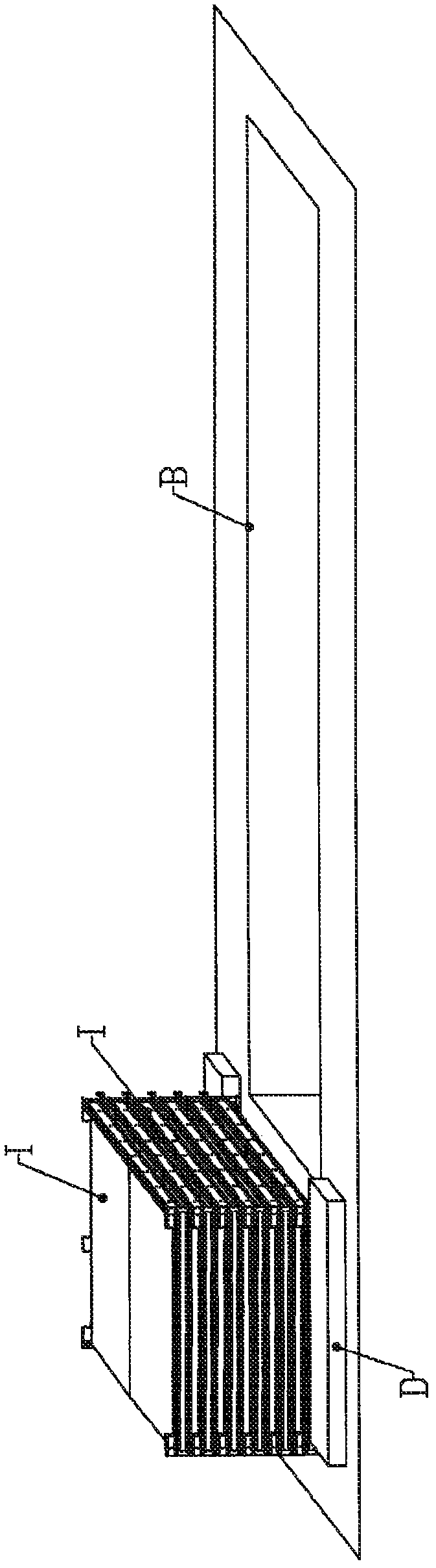
[0041] Such as figure 1 with 2 As shown, a shed marked A is positioned over a recreational pool, marked B, in the form of a swimming pool. This shed A comprises roof parts 1; these roof parts 1 can be moved from a deployed position to a stacked position, wherein said roof parts 1 are juxtaposed in the deployed position, and in the stacked position the roof parts 1 are positioned One bucket is set one above the other and pool B as figure 2 Shown to be partially or fully exposed, the storage area is located at the end of the pool.

[0042] The movement of the roof elements I from a juxtaposed position to a superimposed position and vice versa is carried out by means of a motor-driven device D; the motor-driven device D is shown schematically with a roof The edges of the parts I cooperate with motion transmissions to translate the roof parts I horizontally along the arrow F1 and bring them into a stacked position by inserting the roof parts I into the bottom of the stack. Mo...


PUM


Abstract

The invention relates to a shelter (A) for, for example, a pool- or spa-type recreational basin (B) that is formed of roofing elements (I) and is capable of passing from a deployed position, where the roofing elements are placed in a juxtaposed manner and the basin is covered, to a stacked position, where the roofing elements are placed one over the other and the basin is partially or completely uncovered, said roofing elements (I) including two transverse sections (110 and 120) cross-tied with longitudinal cross-pieces (130), with the so-called extreme cross-pieces (140 and 150) placed on the ends of said sections (110 and 120) that eventually rest on the rim of the basin (B) through a rolling means (300) that is formed of wheels (310) and remarkable in that the wheels (310) are mounted on wheel holders (320) that are foldably mounted relative to the extreme cross-pieces (140 and 150); so as to enable the folding away thereof during the stacking of the roofing elements (I).

Description

technical field [0001] The present invention relates to recreational pools, such as swimming pools, and in particular to adaptation solutions capable of covering them in optimum conditions. Background technique [0002] In the prior art there are sheds for recreational pools such as swimming pools, which are constructed from roof members and can be converted from an unfolded position where the roof members are juxtaposed and the pool is covered to where the roof members are placed one on top of the other and pools are partially or fully exposed overlapping positions. [0003] This transition from one configuration to the other (reversible of course) is effected by motorized or non-motorized movement means. In WO 2005 / 052285 a shed and a motor drive to effectuate the transition from the open position to the deployed position are described. [0004] The inventors have found that, in the stacked position, the roof elements are not small in size and are traditionally placed at...

Claims


Application Information

Patent Timeline
Patent Type & Authority Applications(China)
IPC IPC(8): E04H4/08B63B19/19
CPCB61D39/002B63B19/19E04H4/086
Inventor 克里斯托弗·泊塞威廉姆·特斯图弗雷德里克·维斯塔普
Owner ABRISUD
Why Eureka
Try Eureka