
Load control device with visual indication of energy saving and usage information

A visual display and visual technology, applied in lighting devices, light sources, electrical components, etc., can solve problems such as wasting energy

Inactive Publication Date: 2011-12-21
LUTRON ELECTRONICS CO INC
View PDF14 Cites 15 Cited by
  • Summary
  • Abstract
  • Description
  • Claims
  • Application Information

AI Technical Summary

Problems solved by technology

However, many users of dimmer switches inadvertently control the intensity of lighting loads to a higher level than is actually needed, i.e. higher than needed to provide light, thus wasting energy

Method used


Image

  • Load control device with visual indication of energy saving and usage information
  • Load control device with visual indication of energy saving and usage information
  • Load control device with visual indication of energy saving and usage information

Examples


Embodiment Construction

[0037] The foregoing summary, as well as the following detailed description of the preferred embodiments, are better understood when read with the accompanying drawings. For purposes of illustrating the invention, the presently preferred embodiments are shown in the drawings, wherein like reference numerals represent like parts throughout the drawings, it being understood that the invention is not limited to the particular methods disclosed and means.

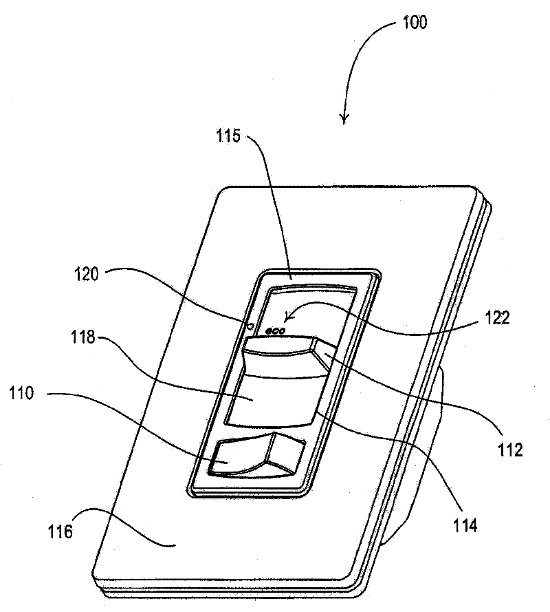
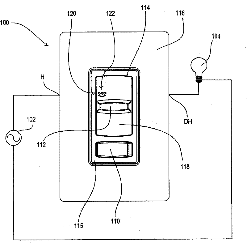
[0038] figure 1 is a perspective view of a dimmer switch 100 providing visual indication of energy saving and usage information in accordance with a first embodiment of the present invention. figure 2 Shown is a front view of a dimmer switch 100 coupled in series electrical connection between an alternating current (AC) power source 102 and a lighting load 104 for controlling the amount of power delivered to the load. The dimmer switch 100 is coupled to a power source 102 via a hot terminal H and to a lighting load 104 via a...


PUM


Abstract

A dimmer switch for controlling the amount of power delivered to and thus the intensity of a lighting load comprises a visual display operable to provide a visual indication representative of energy savings and usage information. The visual display may comprise a single visual indicator or a linear array of visual indicators. The visual display is illuminated in a first manner when the intensity of the lighting load is less than or equal to a predetermined eco-level intensity, and is illuminated in a second manner when the intensity of the lighting load is greater than the eco-level intensity. For example, the single visual indicator may be illuminated a first color, such as green, when the intensity of the lighting load is less than or equal to the eco-level intensity, and illuminated a second different color, such as red, when the intensity of the lighting load is greater than the eco-level intensity.

Description

[0001] related application [0002] This application claims priority to the following commonly assigned application: U.S. Provisional Patent Application Serial No. 61 / 117,624, filed November 25, 2008, and entitled "LOAD CONTROL DEVICE PROVIDING VISUAL INDICATION OF ENERGY ENERGY INFORMATION" THAT PROVIDES A VISUAL INDICATION OF ENERGY SAVING INFORMATION)"; U.S. Provisional Patent Application Serial No. 61 / 139,206, filed December 19, 2008, entitled "LOAD CONTROL APPARATUS FOR PROVIDING VISUAL INDICATION OF ENERGY SAVING INFORMATION" DEVICE PROVIDING A VISUAL INDICATION OF ENERGY USAGE INFORMATION)”; and U.S. Patent Application Serial No. 12 / 363,258, filed January 30, 2009, entitled “LOAD CONTROL DEVICE WITH VISUAL INDICATION OF ENERGY USAGE INFORMATION (LOAD CONTROL DEVICE HAVING A VISUAL INDICATION OF ENERGY SAVINGS AND USAGE INFORMATION)". The entire disclosures of these applications are hereby incorporated by reference. technical field [0003] The present invention relate...

Claims


Application Information

Patent Timeline
Patent Type & Authority Applications(China)
IPC IPC(8): H05B39/08H01H15/02
CPCH01H9/181H01H2231/052H01H15/025H05B39/085
Inventor G·阿尔托宁埃利奥特·G·雅各布C·J·萨尔韦斯特里尼约尔·S·斯皮尔
Owner LUTRON ELECTRONICS CO INC
Learn More