Optical fiber junction box
A fiber optic junction box and axis technology, applied in the direction of light guides, optics, optical components, etc., can solve the problems of communication line protection, communication line interference, damage, etc., and achieve the effect of simple and fast operation, eliminating interference or even damage
- Summary
- Abstract
- Description
- Claims
- Application Information
AI Technical Summary
Problems solved by technology
Method used
Image
Examples
no. 1 example
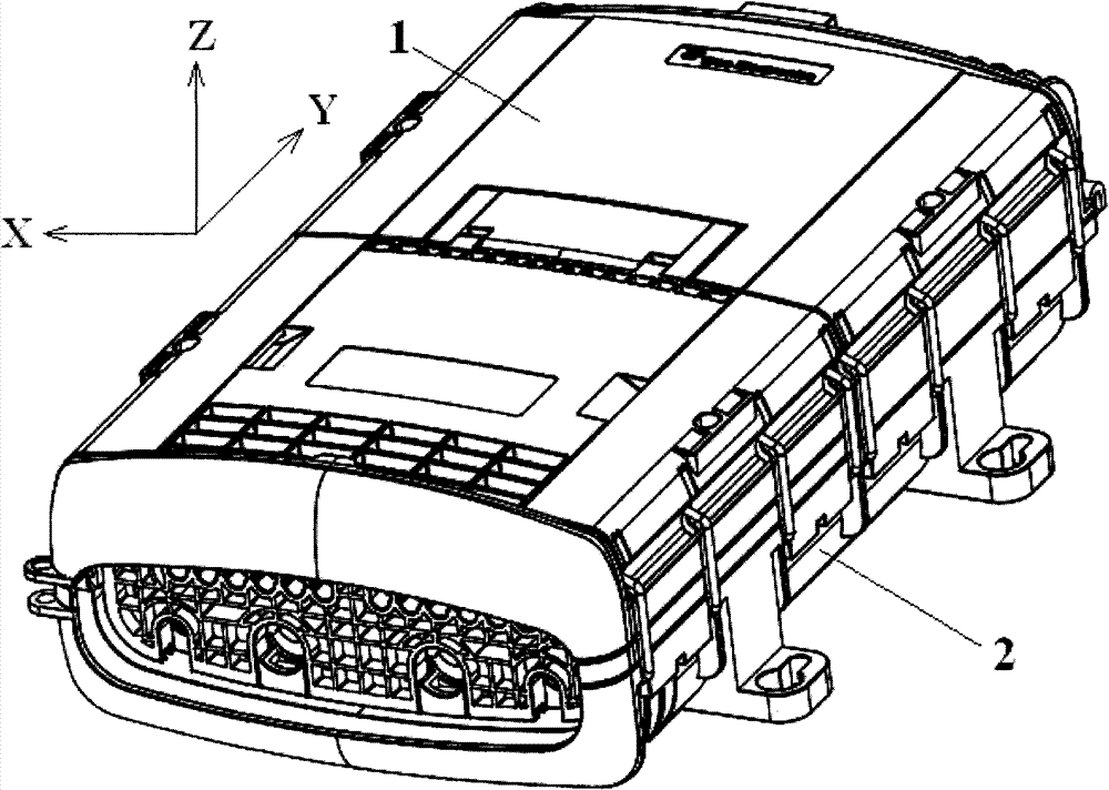
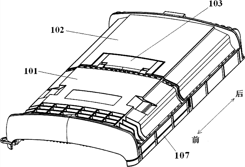
[0034] figure 1 A schematic perspective view of the optical fiber junction box according to the first preferred embodiment of the present invention is shown. like figure 1 As shown, the optical fiber junction box has a housing, which includes a base 2 and a top cover 1 .
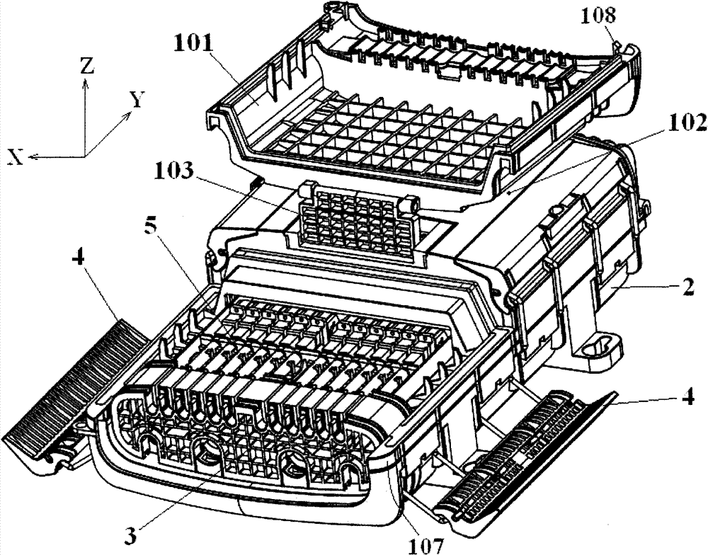
[0035] image 3 A schematic perspective view of the optical fiber junction box according to the first preferred embodiment of the present invention is shown, wherein only the front cover unit is in an open state. like image 3 As shown, a wiring tray 5 is accommodated in the housing, and various operation areas are arranged on the wiring tray 5, such as a wiring operation area for inserting optical fibers, a fusion operation area for fusing trunk optical fibers, and a fiber coil operation area. like image 3 As shown, an elastic sealing block 3 is provided at the port of the housing.
[0036] For the sake of illustration, as figure 1 and image 3 As shown, in this specification, the length direction ...
no. 2 example
[0053] Image 6 A schematic perspective view of an optical fiber junction box according to a second preferred embodiment of the present invention is shown, wherein only the front cover unit is in an open state. Figure 7 A schematic perspective view of an optical fiber junction box according to a second preferred embodiment of the present invention is shown, wherein both the front cover unit and the rear cover unit are in an open state.
[0054] and figure 1 Compared to the first embodiment shown in Figure 5, Image 6 and Figure 7 The difference of the second embodiment shown is only that: the front cover unit 101 and the rear cover unit 102 are rotated and opened around the axis along the length direction Y of the fiber splice box, instead of being rotated and opened around the axis along the width direction X of the fiber optic splice box .
[0055] Specifically, such as Image 6 and Figure 7 As shown, both the front cover unit 101 and the rear cover unit 102 are con...
no. 3 example
[0061] Figure 8 A schematic perspective view of an optical fiber junction box according to a third preferred embodiment of the present invention is shown. like Figure 8 As shown, the top cover 1 is composed of a base cover unit 10 and two sub-cover units 11, 12 for covering two openings 11', 12' on the base cover unit 10.
[0062] exist Figure 8 In the preferred embodiment shown, both sub-cover units 11, 12 are rotatably connected to a base cover unit 10 which in turn is rotatably connected to a base (not shown).
[0063] Of course, the sub-cover units 11 and 12 can also be connected to the base cover unit 10 by snap fit or interference fit, and the base cover unit 10 can also be connected to the base 2 by snap fit or interference fit.
[0064] Although in Figure 8 The preferred embodiment shown comprises two sub-cover units 11, 12, but may also comprise one, three, four or more sub-cover units.
[0065] Similar to the first and second embodiments, the coverage area o...
PUM
 Abstract
Description
Claims
Application Information
 - R&D Engineer
- R&D Manager
- IP Professional
- Industry Leading Data Capabilities
- Powerful AI technology
- Patent DNA Extraction
Browse by: Latest US Patents, China's latest patents, Technical Efficacy Thesaurus, Application Domain, Technology Topic, Popular Technical Reports.
© 2024 PatSnap. All rights reserved.Legal|Privacy policy|Modern Slavery Act Transparency Statement|Sitemap|About US| Contact US: help@patsnap.com


