Integrated type magneto-rheological damper with built-in distance sensors for displacement detection

A distance sensor, displacement detection technology, applied in shock absorbers, shock absorbers, springs/shock absorbers, etc., can solve the problem of affecting the overall reliability and stability of the vibration control system, increase the volume of the control system, and shorten the service life of the system and other problems, to achieve the effect of improving reliability and stability, reducing system volume, and optimizing vibration reduction effect.

CN107882915APending Publication Date: 2018-04-06EAST CHINA JIAOTONG UNIVERSITY
12 Cites 6 Cited by

Patent Information

Authority / Receiving Office
CN · China
Patent Type
Applications(China)
Current Assignee / Owner
Publication Date
2018-04-06

Smart Images

  • Figure 1
    Figure 1
  • Figure 2
    Figure 2
  • Figure 3
    Figure 3
Patent Text Reader

Abstract

The invention discloses an integrated type magneto-rheological damper with built-in distance sensors for displacement detection. The integrated type magneto-rheological damper mainly comprises a piston rod, a dust cover, a capacitive distance sensor I, a capacitive distance sensor II, a damper cylinder barrel, a piston head, an excitation coil, end covers and the like; the capacitive distance sensor I and the capacitive distance sensor II are arranged in the dust cover and are rigidly connected to a left damper end cover of the damper; in the process of external vibration, the dust cover and the damper cylinder barrel move relative to each other, the radial clearances between the inner inclined surface of the dust cover and the two capacitive distance sensors also change, and therefore anoutput signal which corresponds to the displacement of the piston head in proportion is induced; and the current of the excitation coil is adjusted according to the obtained displacement information of the piston head, and therefore the purposes of optimizing the damping effect, improving the damping efficiency and saving energy can be achieved. The integrated type magneto-rheological damper has the advantages of being compact in structure, small in size, high in sensitivity, resistant to pollution, high in anti-interference capability and particularly suitable for a semi-active control systemin a severe working environment.
Need to check novelty before this filing date? Find Prior Art

Description

technical field

[0001] The invention relates to a magnetorheological damper, in particular to an integrated magnetorheological damper with a built-in distance sensor for displacement detection. Background technique

[0002] The magnetorheological damper is a new type of semi-active damping device based on the controllable characteristics of magnetorheological fluid. The device can generate resistance to movement and be used to dissipate the energy of movement. Simple, small in size, easy to control and low energy consumption, it is an ideal vibration isolation and anti-seismic device, and has wide application prospects in construction, machinery, military and other industries.

[0003] Traditional spring dampers are used in various places for vibration reduction, but with people's requirements for vibration reduction effects, the vibration reduction effect of spring dampers is gradually unsatisfactory. The advent of magnetorheological fluid has promoted the development of m...

Examples

Embodiment Construction

[0014] Below in conjunction with accompanying drawing and embodiment the present invention will be further described:

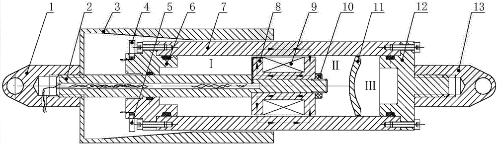
[0015] figure 1 It is a structural schematic diagram of the present invention, mainly including left lug 1, piston rod 2, dust cover 3, capacitive distance sensor I4, capacitive distance sensor II5, damper left end cover 6, damper cylinder 7, piston head 8 , Excitation coil 9, nut 10, floating piston 11, damper right end cover 12 and right lifting lug 13.

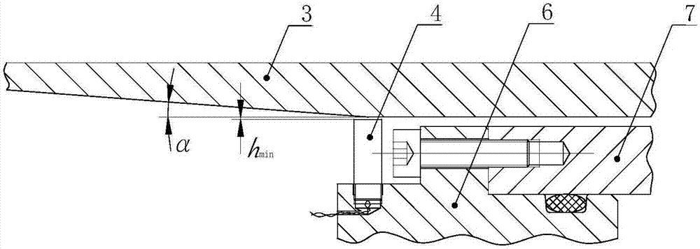
[0016] figure 2 It is a partial schematic diagram when the piston head of the present invention moves to the rightmost end of the stroke. At this time, the radial radial gap between the capacitive distance sensor and the dust cover is the smallest, that is, the attached figure 2 shown h min .

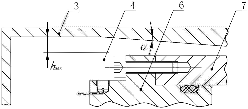
[0017] image 3 It is a partial schematic diagram when the piston head of the present invention moves to the leftmost end of the stroke. At this time, the radial gap between the capacitive distance sensor an...