
DSP (Digital Signal Processor)-based quad-rotor unmanned aerial vehicle autonomous hover control system and method

An unmanned aerial vehicle and control system technology, which is applied in the field of autonomous hovering control of unmanned aerial vehicles, can solve problems such as small load, and achieve the effects of low cost, guaranteed consistency and low price.

Active Publication Date: 2013-10-23
TIANJIN UNIV
View PDF12 Cites 65 Cited by
  • Summary
  • Abstract
  • Description
  • Claims
  • Application Information

AI Technical Summary

Problems solved by technology

However, the platform has certain limitations, mainly because of its small load and can only fly in an indoor environment (Journal: IEEE International Conference on Robotics and Automation; Author: S.Shen, N.Michael, V.Kumar; Published: 2011 Article title: Autonomous Multi-Floor Indoor Navigation with a Computationally Constrained MAV, page number: 20-25); (3) Researchers from the National University of Defense Technology in China designed and produced a four-rotor unmanned aerial vehicle body and a single-chip microcomputer as a control unit Airborne control system, and achieved good control effect in the simulation (Journal: China National University of Defense Technology Master's Degree Thesis; Author: Wang Junsheng; Published: 2007; Title: Design of Quadrotor Butterfly Aircraft Control System and control method research; pages: 12-22)

Method used


Image

  • DSP (Digital Signal Processor)-based quad-rotor unmanned aerial vehicle autonomous hover control system and method
  • DSP (Digital Signal Processor)-based quad-rotor unmanned aerial vehicle autonomous hover control system and method
  • DSP (Digital Signal Processor)-based quad-rotor unmanned aerial vehicle autonomous hover control system and method

Examples


Embodiment Construction

[0051] The DSP-based four-rotor unmanned aerial vehicle autonomous hovering control system and method of the present invention will be described in detail below in conjunction with the embodiments and accompanying drawings.

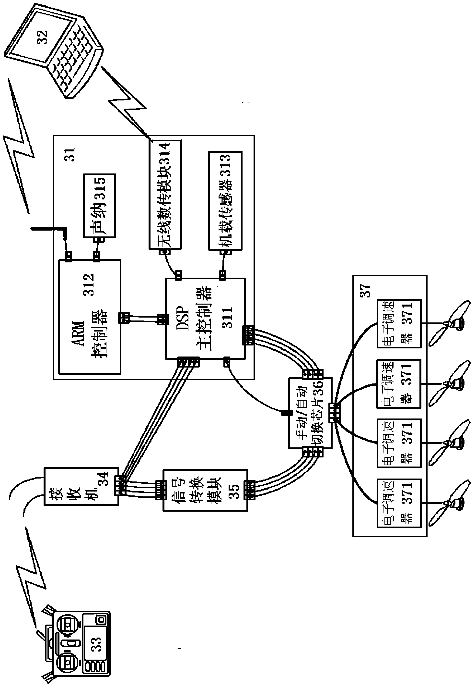
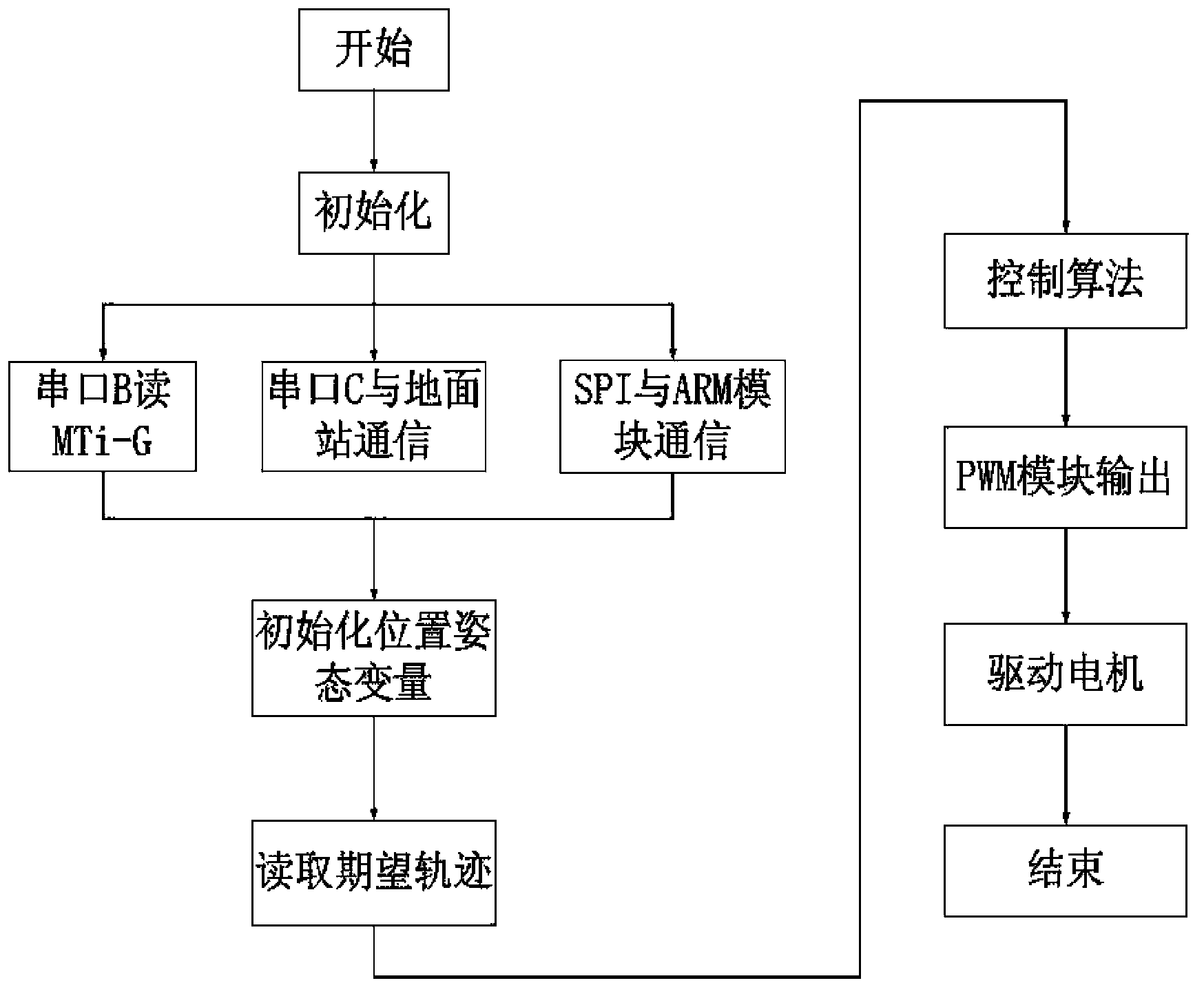
[0052] Such as figure 1 , figure 2 As shown, the DSP-based four-rotor unmanned aerial vehicle autonomous hover control system of the present invention includes a four-rotor body 1, four propellers 2 respectively arranged on four wings and a control unit for controlling the rotation of four propellers 2 3.

[0053] 1. The four-rotor body 1 is a four-rotor unmanned aerial vehicle that comprehensively considers the structural stability, load capacity, endurance, controllability and other characteristics of the aircraft body. The diameter of the fuselage is 450mm, the height is 111mm; the empty weight is 750g (excluding receiver and battery), the load weight is 750g, and the maximum safe take-off total weight is 1500g; the diameter of the propeller is 25....


PUM


Abstract

The invention discloses a DSP (Digital Signal Processor)-based quad-rotor unmanned aerial vehicle autonomous hover control system and method. The control system is provided with four screw propellers and control units which are arranged on four airfoils respectively; and each control unit is that a master control unit is connected to a ground computer through a wireless network, and a receiver is connected with a signal conversion module and a manual / automatic switching chip in sequence, transmits a received signal transmitted by a remote controller into the manual / automatic switching chip through the signal conversion module, is also connected with the manual / automatic switching chip through the master control unit and is used for transmitting the received signal to the manual / automatic switching chip through the master control unit for controlling driving units to drive direct current brushless motors on the four screw propellers to work. According to the method, kalman filtering processing is performed on sonar data to obtain accurate height data and driver control. According to the system and the method, the autonomous flight capacity of a micro quad-rotor unmanned aerial vehicle and the adaptability to the environment can be effectively enhanced, and the autonomous flight control under indoor environments and outdoor environments can be finished.

Description

technical field [0001] The invention relates to an autonomous hovering control method of an unmanned aerial vehicle. In particular, it relates to a DSP-based four-rotor unmanned aerial vehicle autonomous hovering control system and method. Background technique [0002] An unmanned aerial vehicle refers to an unmanned, autonomously propelled aircraft that is controlled by radio remote control or its own program, uses aerodynamics to fly, and can be recycled and reused. With its own advantages and characteristics, it has been widely used in many fields. In military terms, the main uses of unmanned aerial vehicles include ground battlefield reconnaissance, obtaining enemy intelligence, close-range control patrols, surveillance, electronic warfare, ground communications, etc.; And image transmission, patrol monitoring and target tracking, search and rescue after natural disasters, inspection of high-voltage lines, bridges, dams and road sections after earthquakes, etc. UAVs c...

Claims


Application Information

Patent Timeline
Patent Type & Authority Applications(China)
IPC IPC(8): G05D1/10
Inventor 鲜斌赵勃黄国平
Owner TIANJIN UNIV
Learn More