Developing shaft component of blueprinting machine

A technology of shaft components and image printing machines, which is applied in photography, optics, instruments, etc., can solve the problems of reducing image printing speed, low efficiency, environmental pollution, etc., and achieves the effect of convenient and rapid development

Inactive Publication Date: 2012-01-25
WUXI HENGYUAN OFFICE MACHINERY
View PDF0 Cites 0 Cited by
  • Summary
  • Abstract
  • Description
  • Claims
  • Application Information

AI Technical Summary

Problems solved by technology

In the operation and use of many printing machines, due to the limitation of the mechanical structure, the method of ammonia water fumigation is usually used for development. This processing method is inefficient, pollutes the environment, is not suitable for manual operation, and reduces the printing speed, which is very inconvenient.

Method used


Image

  • Developing shaft component of blueprinting machine
  • Developing shaft component of blueprinting machine

Examples


Embodiment Construction

[0009] Below the present invention will be further described in conjunction with the embodiment in the accompanying drawing:

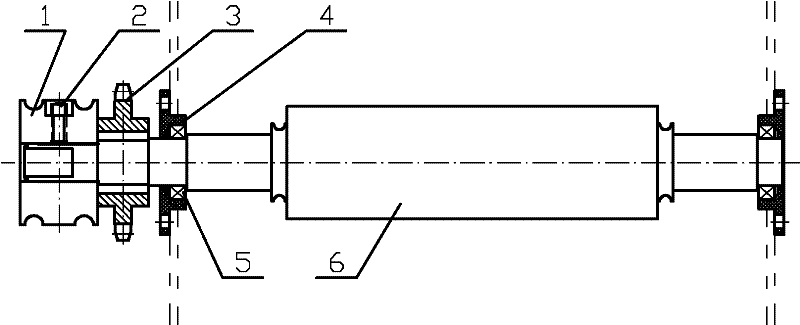
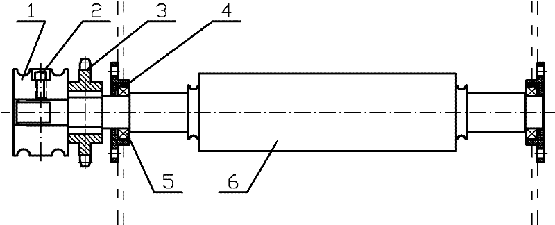
[0010] Such as figure 1 As shown, it includes O-ring belt pulley 1, O-ring belt pulley set screw 2, developing shaft transmission sprocket 3, bearing housing 4, bearing 5, and developing shaft 6.

[0011] A bearing 5 is embedded in the bearing seat 4; a developing shaft 6 is embedded in the bearing seat 4, the developing shaft drive sprocket 3 and the O-ring pulley 1 in sequence.

[0012] The O-ring pulley 1 is fixed on the developing shaft 6 through the O-ring pulley set screw 2 . The developing shaft 6 is a rubber shaft, the surface of which is coated with developer.

[0013] When working, through the action of the developing shaft, under the uniform pressure of the upper platen, the transmitted printing paper is brought into contact with the developing shaft, and the developer on the surface of the developing shaft is taken away, so that the print...


PUM


Abstract

The invention relates to a developing shaft component of an ammonia-free blueprinting machine, belonging to the technical field of office machinery. The developing shaft component comprises a developing shaft and is characterized by also comprising an O-shaped ring belt wheel, an O-shaped ring belt wheel fastening screw, a developing shaft transmission chain wheel, a bearing seat and a bearing, wherein the bearing seat is embedded into the bearing; and the developing shaft is sequentially embedded into the bearing seat, and the developing shaft transmission chain wheel and the O-shaped ring belt wheel. The O-shaped ring belt wheel is fixed onto the developing shaft by virtue of the O-shaped ring belt wheel fastening screw. In the invention, under the action of the developing shaft, blue printing paper which is conveyed is contacted with the developing shaft, a developing solution on the surface of the developing shaft is taken away, and the blue printing paper can be conveniently, rapidly and effectively developed.

Description

technical field [0001] The invention relates to a developing shaft part of an ammonia-free printing machine, in particular to a developing shaft part for a 5000PD printing machine, and belongs to the technical field of office machinery. Background technique [0002] In various manufacturing industries and engineering construction, drawings (blueprints) are used in large quantities. In the operation and use of many photo printing machines, due to the limitation of the mechanical structure, ammonia water fumigation is usually used to develop the photo. This processing method is inefficient, pollutes the environment, is not suitable for manual operation, and reduces the photo printing speed, which is very inconvenient. Contents of the invention [0003] The purpose of the present invention is to overcome the deficiencies in the prior art, and to provide a developing shaft part of an ammonia-free printing machine for effective development of copied originals through the action...

Claims


Application Information

Patent Timeline
Patent Type & Authority Applications(China)
IPC IPC(8): G03D5/06
Inventor 刘善虎
Owner WUXI HENGYUAN OFFICE MACHINERY
Why Eureka
Try Eureka