LCD (liquid crystal display) data driven IC (integrated circuit) output compensation circuit and compensation method

A data-driven, output compensation technology, applied in nonlinear optics, instruments, optics, etc., can solve the problems of inability to meet the winding space, uneven screen display, shrinking of the winding space, etc., and is conducive to narrow frame design, improvement EMI problems, the effect of small trace space

Active Publication Date: 2012-04-04
TCL CHINA STAR OPTOELECTRONICS TECH CO LTD
View PDF6 Cites 53 Cited by
  • Summary
  • Abstract
  • Description
  • Claims
  • Application Information

AI Technical Summary

Problems solved by technology

In this way, when the scan line turns on a certain row of pixels, all the output channels of the data driver IC3 output at the same time. At this time, the impedance of the data lines of each row is the same, so the time for charging each pixel of the same row is the same, so that the screen On the contrary, when the data line impedance design is inconsistent, the charging time of each pixel in the same row will be different, and the screen display corresponding to the data line control area will have uneven problems
[0004] However, with the increase in the number of output channels of a single data-driven IC3, in order to meet the output compensation, the space required for wiring in a serpentine shape will increase. The space will gradually shrink. Therefore, the existing serpentine data line routing method cannot meet the requirements of a narrow-frame liquid crystal display with a small winding space and uniform screen display.
In addition, the current output channels of the data driver IC3 are basically output at the same time, so that when all the output channels are turned on at the same time, a large current needs to be provided to the glass substrate, resulting in EMI (Electro Magnetic Interference, electromagnetic interference) The problem

Method used


Image

  • LCD (liquid crystal display) data driven IC (integrated circuit) output compensation circuit and compensation method
  • LCD (liquid crystal display) data driven IC (integrated circuit) output compensation circuit and compensation method
  • LCD (liquid crystal display) data driven IC (integrated circuit) output compensation circuit and compensation method

Examples


Embodiment Construction

[0032] It should be understood that the specific embodiments described herein are only used to explain the present invention, but not to limit the present invention.

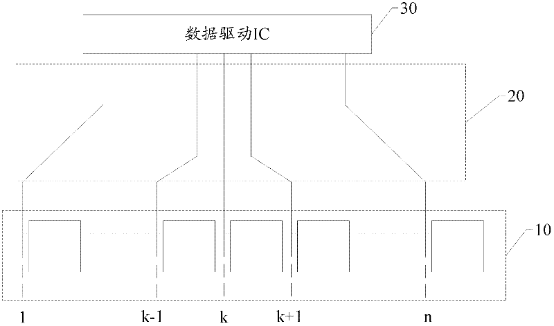
[0033] The main solution of the present invention is to set the output control switch on the output channel of the data drive IC, and turn on the switch on each output channel step by step according to the impedance value of each data line through the delay control unit, so that each output channel on the glass substrate The charging time of each pixel electrode in a row is the same, which ensures the uniformity of the picture display, and the data line does not need to adopt a serpentine routing method, which reduces the winding space and is beneficial to the narrow frame design of the liquid crystal display.

[0034] Please refer to figure 2 and image 3 As shown, figure 2 This is a schematic structural diagram of the data line output by the data driving IC of the present invention without winding wires and chargi...


PUM


Abstract

The invention relates to an LCD (liquid crystal display) data driven IC (integrated circuit) output compensation circuit and a compensation method. The circuit comprises a data driven IC, a plurality of first switching unit and a delay control unit. A plurality of output channels of the data driven IC are respectively connected with pixel electrodes on corresponding lines in a glass substrate through data lines and output charging signals to charge the pixel electrodes on the corresponding lines; each output channel is provided with one first switching unit for controlling the output channel on which the first switching unit is positioned according to delay control signals generated by the delay control unit and outputting the charging signals according to preset delayed time; and the delay control unit generates the corresponding delay control signals according to impedance values of the corresponding data lines so as to control to start the corresponding first switching unit according to the preset delayed time and ensure each pixel electrode to have equal charging time. The LCD data driven IC output compensation circuit does not need to be wound with a wire; the routing space of the glass substrate is reduced, the LCD data driven IC output compensation circuit is beneficial to the design of a narrow border of a liquid crystal display, and the EMI (Electro Magnetic Interference) problem generated when all the output channels are simultaneously opened are improved.

Description

Technical field [0001] The present invention relates to the technical field of liquid crystal display, and in particular to an LCD data drive IC output compensation circuit and a compensation method that are beneficial to the design of a narrow frame of a liquid crystal display. Background technique [0002] Such as figure 1 As shown, when the data line 2 in the liquid crystal panel is output from a data driver IC (Integrated Circuit, integrated circuit) 3, in order to make the signal of each data line 2 reach each pixel in each row at the same time, each line is routed. The impedance of each data line 2 should be basically the same. [0003] In the prior art, in order to make the impedance of each trace basically the same when reaching each pixel, a section of serpentine trace is usually used for implementation. The data line 2 will be connected to the pixel area 1 through a section of serpentine winding. According to the material and length of the data line 2, the impedance of e...

Claims


Application Information

Patent Timeline
Patent Type & Authority Applications(China)
IPC IPC(8): G09G3/36
CPCG09G2330/06G09G2320/0223G09G2310/08G09G3/3685G09G3/36G02F1/133G02F1/1345G09G2320/0233
Inventor 廖良展林柏伸郭东胜
Owner TCL CHINA STAR OPTOELECTRONICS TECH CO LTD
Why Eureka
Try Eureka