
Hydrogen fuel cell power system and chopper circuit control system and method

A chopper circuit and control system technology, applied in control/regulation systems, electrical components, regulating electrical variables, etc., can solve problems such as excessive ripple current

Active Publication Date: 2021-01-29
SHENZHEN AUTOMOTIVE RES INST BEIJING INST OF TECH (SHENZHEN RES INST OF NAT ENG LAB FOR ELECTRIC VEHICLES)
View PDF6 Cites 0 Cited by
  • Summary
  • Abstract
  • Description
  • Claims
  • Application Information

AI Technical Summary

Problems solved by technology

[0004] This application discloses a chopper circuit control system to solve the technical problem of excessive ripple current of the interleaved coupled Boost circuit under high power

Method used


Image

  • Hydrogen fuel cell power system and chopper circuit control system and method
  • Hydrogen fuel cell power system and chopper circuit control system and method
  • Hydrogen fuel cell power system and chopper circuit control system and method

Examples


Embodiment 1

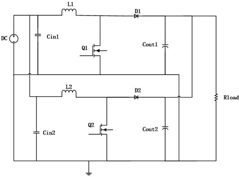
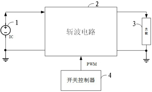
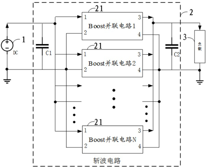
[0039] Please refer to figure 2 , is a schematic diagram of the structural connection of the chopper circuit control system in an embodiment, including a DC power supply 1 , a load 3 , a chopper circuit 2 and a switch controller 4 . The chopper circuit control system is used to convert the first DC power supply into the output of the second DC power supply, and the chopper circuit control system includes a chopper circuit 2 and a switch controller 4 . Please refer to image 3 , is a schematic diagram of the structural connection of the chopper circuit in an embodiment, the chopper circuit 2 includes at least one set of Boost parallel circuits 21 . Please refer to Figure 4 , is a schematic diagram of the structural connection of the Boost parallel circuit in an embodiment, the Boost parallel circuit 21 includes two magnetically coupled Boost circuits 211 connected in parallel, as Figure 4 Boost circuit 1 and Boost circuit 2 are shown. Each Boost circuit 211 includes a fi...

Embodiment 2

[0046] Please refer to Figure 6 , which is a flowchart of a chopper circuit control method in another embodiment, including:

[0047] Step 100, controlling the wave sending sequence of the chopper circuit.

[0048] The wave transmission timing of the two Boost circuits controlling each group of Boost parallel circuits is out of phase by 180 degrees. Wherein, the chopper circuit includes at least one set of Boost parallel circuits, and the Boost parallel circuit includes two magnetically coupled Boost circuits connected in parallel.

[0049] In one embodiment, the chopper circuit control method further includes:

[0050] Step 200, controlling the working mode of the chopper circuit.

[0051] The control chopper circuit works in CCM mode.

[0052] In one embodiment, the chopper circuit includes N sets of Boost parallel circuits, where N is an integer greater than 2. The chopper circuit control method also includes:

[0053] Step 300, controlling the timing of sending wave...


PUM


Abstract

The invention relates to a chopper circuit control system, which is used for converting a first direct-current power supply into a second direct-current power supply to be output and comprises a chopper circuit and a switch controller. The chopper circuit comprises at least one group of Boost parallel circuits, each Boost parallel circuit comprises two Boost circuits which are magnetically coupledand connected in parallel, and the switch controller is used for controlling the on-off state of a power switch tube of the chopper circuit and controlling the phase dislocation of wave sending timesequences of the two Boost circuits of each group of Boost parallel circuits by 180 degrees when the first direct-current power supply is input. Due to the fact that the two Boost circuits in the Boost parallel circuit are connected in parallel in a magnetic coupling mode, reverse recovery loss and zero-current switching-on of power switch tubes of the Boost circuits are achieved, the circuit efficiency is improved, the EMI problem caused by the switch controller is solved, and the technical problem that ripple currents of the cross-coupled Boost circuits are too large under high power is solved.

Description

technical field [0001] The invention relates to the technical field of new energy photovoltaics and fuel cells, in particular to a hydrogen fuel cell power system, a chopper circuit control system and a method. Background technique [0002] Microgrid technology represents the development trend of distributed energy supply systems in the future and is an important part of the future intelligent power distribution system. It is of great significance to promote energy conservation and emission reduction and achieve sustainable energy development. Photovoltaic and fuel cell technologies in new energy have become ideal ways of future household new energy power generation due to their wide application range, short construction period, and clean and pollution-free features. However, the remarkable characteristics of these two power supplies are low output voltage and wide-range fluctuations, which require a high-gain DC converter in the previous stage to perform step-up conversion ...

Claims


Application Information

Patent Timeline
IPC IPC(8): H02M3/158
CPCH02M3/1584
Inventor 王文伟韦景豹
Owner SHENZHEN AUTOMOTIVE RES INST BEIJING INST OF TECH (SHENZHEN RES INST OF NAT ENG LAB FOR ELECTRIC VEHICLES)
Learn More