
Coaxial type hydraulic retarding braking device
A kind of retarding braking, coaxial technology, applied in the direction of hydraulic brake transmission, brake transmission, control device, etc., can solve the problem of the urgency of deploying retarder on heavy vehicles, achieve light weight, easy installation and Modification, soft braking effect
- Summary
- Abstract
- Description
- Claims
- Application Information
AI Technical Summary
Problems solved by technology
Method used
Image

Examples
Embodiment Construction
[0017] The present invention will be described in further detail below in conjunction with the accompanying drawings and specific embodiments.
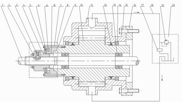
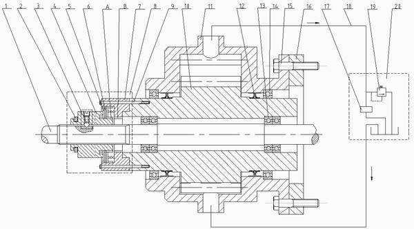
[0018] Such as figure 1 As shown, a coaxial hydraulic retarding brake device includes a transmission shaft 1 , a shift fork 2 , a positioning mechanism 3 , a clutch assembly 8 , an oil pump rotor 10 , an oil pump housing 11 and an oil pressure control system 20 .
[0019] Wherein, the oil pump rotor 10 is a hollow rotating shaft, and bearings 13 are respectively installed in both ends of the inner hole of the oil pump rotor 10, and the oil pump rotor 10 is sleeved on the transmission shaft 1 through the bearings 13 and is axially fixed with the transmission shaft 1 and can rotate radially Cooperate. Bearings 14 are installed at both ends of the outer circle of the oil pump rotor 10, and the oil pump housing 11 is sleeved on the oil pump rotor 10 through the shaft sleeve 14 and is axially fixed and radially rotatable with the oil ...
PUM
 Abstract
Description
Claims
Application Information