
SMD type I-shaped quadruped linear ultrasonic motor vibrator
A technology of linear ultrasonic motor and SMD technology, which is applied in the direction of generators/motors, piezoelectric effect/electrostrictive or magnetostrictive motors, electrical components, etc., and can solve difficult miniaturization, processing and assembly precision requirements Harsh, complex configuration and other issues, to achieve the effect of improving consistency, simplifying processing and assembly process, and flexible design
- Summary
- Abstract
- Description
- Claims
- Application Information
AI Technical Summary
Problems solved by technology
Method used
Image

Examples
specific Embodiment approach 1
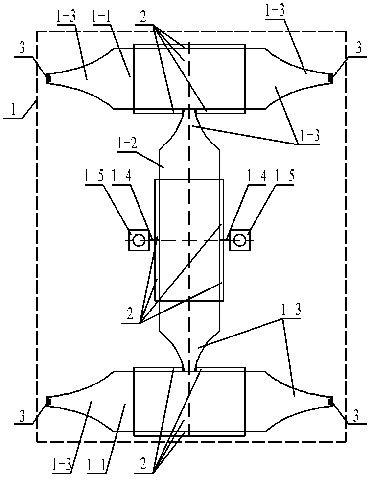
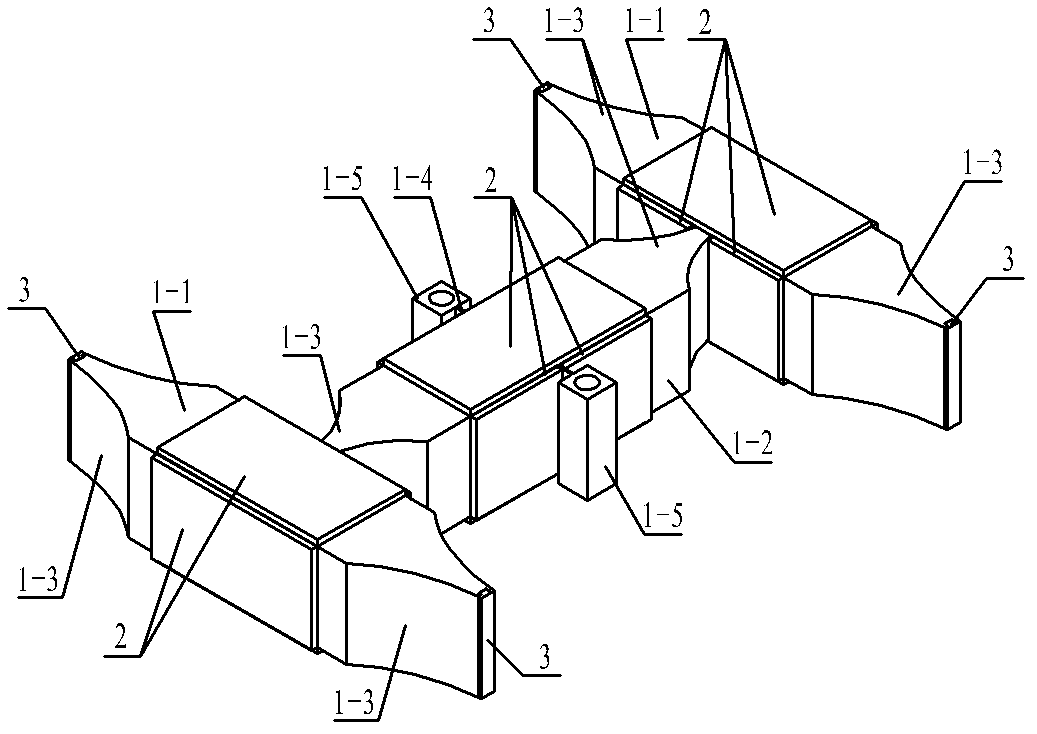
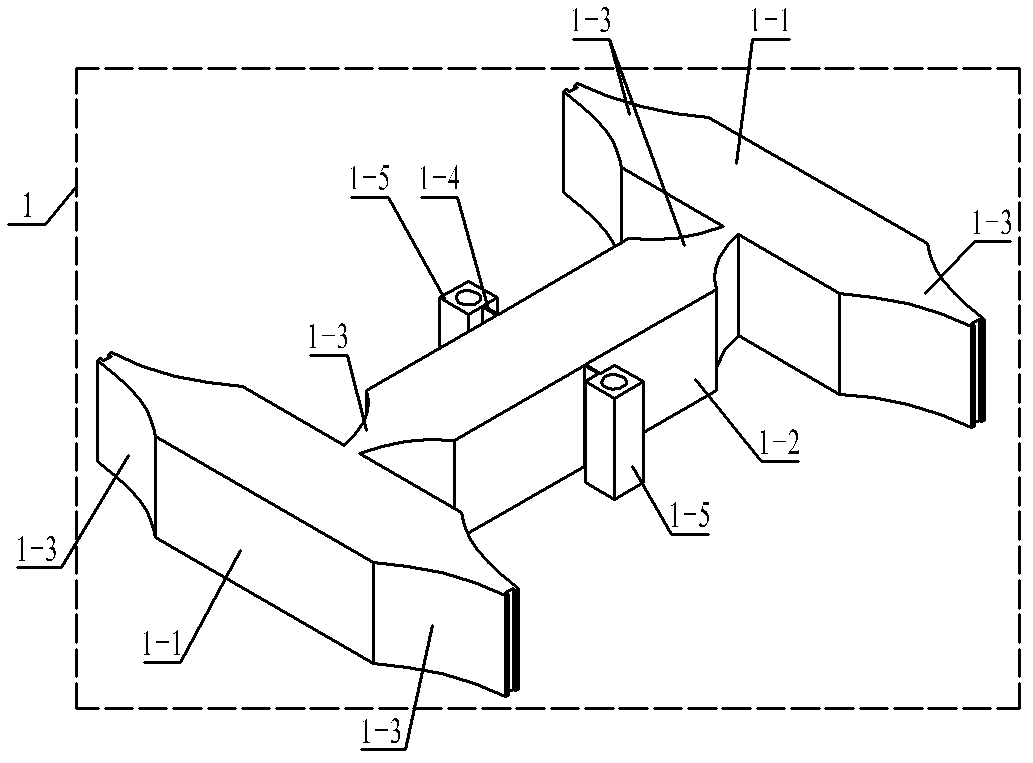
[0011] Specific implementation mode 1. Combination Figure 1 to Figure 3 Describe this embodiment, the chip-type I-shaped quadruped linear ultrasonic motor vibrator described in this embodiment includes an I-shaped metal substrate 1 and a piezoelectric ceramic sheet 2; the I-shaped metal substrate 1 includes two horizontal beams 1 -1, one vertical beam 1-2, six horns 1-3, two thin-walled beams 1-4 and two mounting bases 1-5, the horizontal beam 1-1 and the vertical beam 1-2 are It is a quadrangular prism with a rectangular cross-section, and each horn 1-3 is a quadrangular prism with a rectangular cross-section that gradually becomes thinner, and each of the two end faces of the vertical beam 1-2 is provided with a horn 1-3, and the combined end face of the vertical beam 1-2 and each horn 1-3 is the large end face of the horn 1-3, and the two end faces of each horizontal beam 1-1 are A horn 1-3 is provided, and the end face of the horizontal beam 1-1 combined with each horn 1...
specific Embodiment approach 2
[0012] Embodiment 2. The difference between this embodiment and the patch-type I-shaped quadruped linear ultrasonic motor vibrator described in Embodiment 1 is that the outer side wall, upper side wall and lower side wall of each horizontal beam 1-1 A piece of piezoelectric ceramic sheet 2 is arranged in the center, and two piezoelectric ceramic sheets 2 are arranged on the side wall of each horizontal beam 1-1 connected with the horn 1-3, and the two piezoelectric ceramic sheets The sheet 2 is symmetrically located on the left and right sides of the connection between the horizontal beam 1-1 and the horn 1-3, and a piezoelectric ceramic sheet 2 is centrally arranged on the upper side wall and the lower side wall of the vertical beam 1-2. , the inner and outer walls of the vertical beam 1-5 are provided with two piezoelectric ceramic sheets 2, and the two piezoelectric ceramic sheets 2 are symmetrically arranged on both sides of the thin-walled beam 1-4 on the side wall.
[00...
specific Embodiment approach 3
[0015] Embodiment 3. The difference between this embodiment and the patch-type I-shaped quadruped linear ultrasonic motor vibrator described in Embodiment 1 is that the I-shaped metal base 1 is integrated, which can simplify the processing and assembly process and ensure Precision.
PUM
 Abstract
Description
Claims
Application Information