Model deflection sedimentation control device for geotechnical centrifuge test

A geotechnical centrifuge and settlement control technology, applied in measuring devices, using stable tension/pressure testing materials strength, instruments, etc., can solve the problem of not being able to accurately grasp the impact of uneven settlement of embankment filling and uneven deformation of roadbed surface It can solve the problems of law, uneven deformation of model embankment filling, uneven settlement of subgrade surface, etc., to achieve the effect of compact structure, small space occupation and high reliability.

Inactive Publication Date: 2013-10-16
SOUTHWEST JIAOTONG UNIV
View PDF4 Cites 0 Cited by
  • Summary
  • Abstract
  • Description
  • Claims
  • Application Information

AI Technical Summary

Problems solved by technology

At present, the commonly used simulation method for foundation deflection settlement in geotechnical centrifugal model tests is: first fill model foundations with different strengths at the bottom of the model box, then place the model embankment on the model foundation, and apply centrifugal force to the model in the model box , causing the deflection deformation of the model foundation, which in turn causes the uneven deformation of the model embankment fill and the uneven settlement of the subgrade surface
Due to the poor controllability of the local differential deformation of the model foundation with different strengths, it is impossible to accurately grasp the influence of the deflection deformation of the foundation on the uneven deformation of the embankment fill and the uneven settlement of the subgrade surface

Method used


Image

  • Model deflection sedimentation control device for geotechnical centrifuge test
  • Model deflection sedimentation control device for geotechnical centrifuge test
  • Model deflection sedimentation control device for geotechnical centrifuge test

Examples


Embodiment

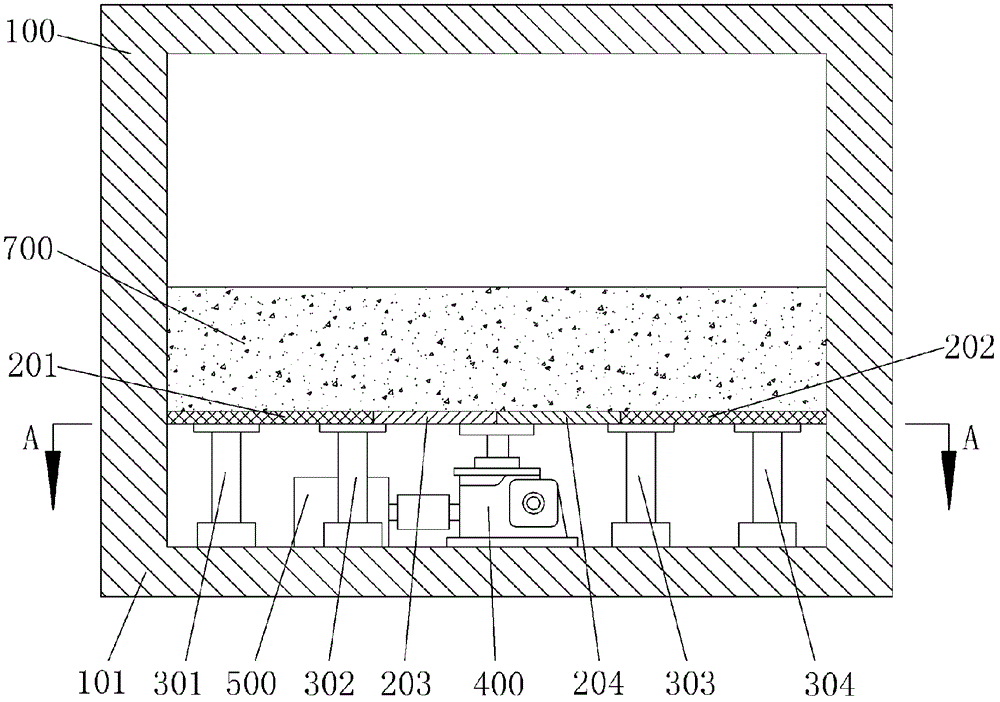
[0023] Figure 1~3 Shown, a kind of embodiment of the present invention is, a kind of model deflection type settlement control device of geotechnical centrifuge test, and it is composed of:

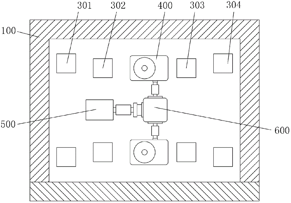
[0024] The left side of the bottom 101 of the model box 100 is fixed with two rows of left support piers 301,302, and the two rows of left support piers 301,302 are supported with a left fixed plate 201; the right side of the bottom of the box 101 is fixed with two rows of right support piers 303, 304, the two rows of right support piers 303, 304 are supported with a right fixed plate 202;

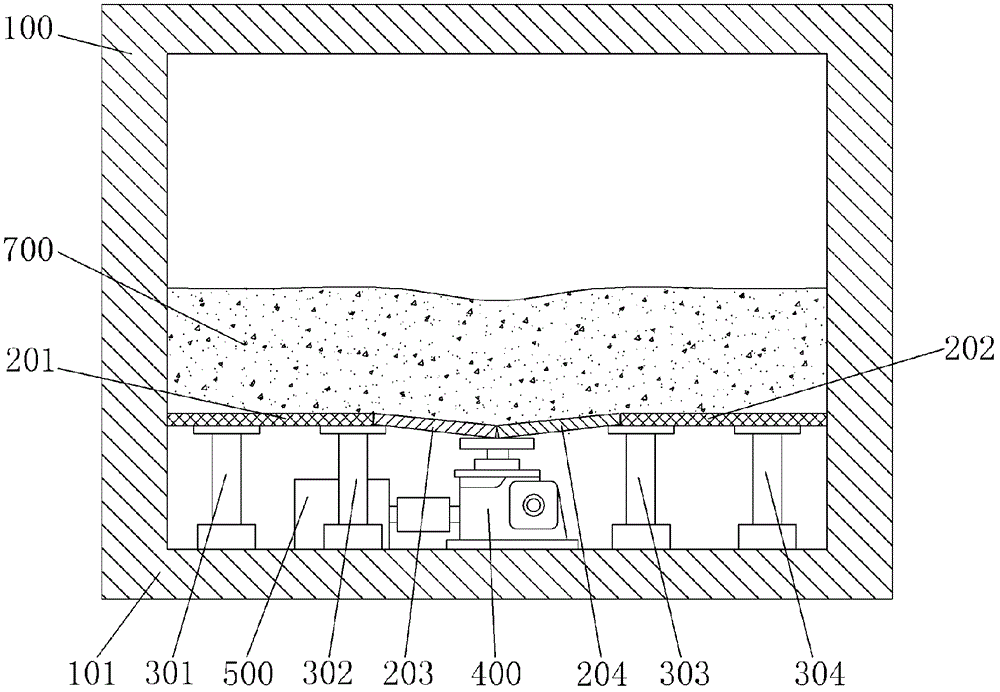
[0025] A row of elevators 400 is fixed in the middle of the bottom of the box 101. The right end of the left inclined plate 203 is lapped on the flange of the elevator 400, and the left end is lapped on the left support pier 302 adjacent to the elevator 400; Connected to the flange of the elevator 400, the right end is lapped on the right supporting pier 303 adjacent to the elevator 400;

[0026] Th...


PUM


Abstract

The invention discloses a model deflection sedimentation control device for geotechnical centrifuge testing. In the control device, two rows of left and right support piers are fixed on the left and right sides of the casing bottom of a model casing respectively; left and right unmovable plates are supported on the two rows of left and right support piers respectively; a row of elevators is fixed in the middle of the casing bottom; the central ends of left and right oblique plates are aligned and lapped on ring flanges of the elevators; the other ends of the left and right oblique plates are lapped on the support piers on both sides adjacent to the elevators respectively; road embankment models are filled on the unmovable plates and the oblique plates; the elevators are connected with a stepping servo motor through a steering box arranged at the casing bottom; and the stepping server motor is electrically connected with an external control system of a geotechnical centrifuge. According to the device, real-time accurate control over model deflection sedimentation can be realized in the running state of the centrifuge, so that the delivery and diffusion rules of deflection non-uniform deformation of a foundation in embankment fill and the influence on the precipitation property of a road bed are grasped, and reliable testing bases are provided for non-uniform sedimentation control of subgrade structures in railway and highway engineering.

Description

technical field [0001] The invention relates to a geotechnical centrifugal model test device, in particular to a model settlement control device for a geotechnical centrifugal model test. Background technique [0002] The subgrade of railway and highway is a belt structure. When the subgrade crosses the valley and the foundation of the embankment has local weakness or karst or caves, the subgrade is prone to deflection settlement, resulting in uneven rail surface and uneven road surface. As a result, severe vibration is caused when the vehicle passes at high speed, which affects the riding comfort and driving stability, and even endangers driving safety in severe cases. The deflection settlement of the subgrade is mainly caused by the local subsidence of the foundation. Through experiments, the inhomogeneous deflection deformation of the foundation, the transmission law of the settlement in the embankment fill, and the uneven settlement characteristics of the subgrade surfac...

Claims


Application Information

Patent Timeline
Patent Type & Authority Patents(China)
IPC IPC(8): G01N3/02G01N3/08
Inventor 罗强陈虎张良杨广伟万小全冉涛魏永权张立祥陈坚刘刚
Owner SOUTHWEST JIAOTONG UNIV
Why Eureka
Try Eureka