Hearing aid with antenna

A technology for hearing aids and antenna elements, applied in hearing aids, antennas, resonant antennas, etc., to solve problems such as radio frequency antenna limitations

Active Publication Date: 2012-05-09
GN HEARING AS
View PDF7 Cites 17 Cited by
  • Summary
  • Abstract
  • Description
  • Claims
  • Application Information

AI Technical Summary

Problems solved by technology

The combination of many electronic and metallic components with the small size of the hearing aid housing pl...

Method used


Image

  • Hearing aid with antenna
  • Hearing aid with antenna
  • Hearing aid with antenna

Examples


Embodiment Construction

[0060] The present invention will now be described more fully hereinafter with reference to the accompanying drawings, in which exemplary embodiments of the invention are shown. However, this invention may be embodied in different forms and should not be construed as limited to the embodiments set forth herein. Rather, these embodiments are provided so that this disclosure will be thorough and complete, and will fully convey the scope of the invention to those skilled in the art.

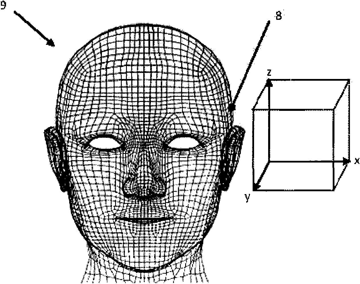
[0061] Hereinafter, a parallel antenna or a parallel section of an antenna refers to an antenna or an antenna section, respectively, in a device which is worn at the user's ear during use and which mainly runs along parallel lines at the user's ear. The head surface or in other words conducts current in a direction perpendicular to the user's interaural axis, and orthogonal antennas or orthogonal sections of antennas refer to antennas or sections of antennas, respectively, in a device that is used i...


PUM


Abstract

The present invention provides a hearing aid with an antenna, wherein the hearing aid includes a housing, and a hearing aid assembly accommodated in a housing, the hearing aid assembly having a first antenna element configured for emission of an electromagnetic field, and a second antenna element comprising a first section and a parasitic antenna element, wherein the first antenna element, the first section, and the parasitic antenna element are configured so that a total electromagnetic field emitted from the hearing aid assembly is substantially the same irrespective of whether the housing is worn in its operational position on a right hand side or a left hand side of a user.

Description

technical field [0001] The present application relates to a hearing aid system adapted for wireless data communication. During operation, the hearing aids worn at opposite ears of a user may communicate wirelessly with each other. Background technique [0002] Hearing aids are very small and delicate devices and include many electronic and metal components housed in a housing small enough to fit behind a person's ear canal or outer ear. The many electronic and metallic components combined with the small size of the hearing aid housing place strong constraints on the design of radio frequency antennas used in hearing aids with wireless communication capabilities. [0003] Traditionally, antennas in hearing aids have been used to receive radio broadcasts or commands from remote controls. Usually, such antennas are designed to be suitable for fitting in a hearing aid housing, without particular regard to the directivity of the resulting radiation pattern obtained. For exampl...

Claims


Application Information

Patent Timeline
IPC IPC(8): H04R25/00
CPCH01Q1/273H04R2225/51H01Q1/243H01Q9/42H04R25/554H01Q1/36H04R25/00H04R25/552
Inventor 希纳西·厄兹登
Owner GN HEARING AS
Why Eureka
Try Eureka