Infrared camera systems and methods for dual sensor applications

A sensor, infrared sensor technology, used in parts of TV systems, parts of color TVs, TVs, etc.

Active Publication Date: 2012-05-16
FLIR SYST INC
View PDF4 Cites 36 Cited by
  • Summary
  • Abstract
  • Description
  • Claims
  • Application Information

AI Technical Summary

Problems solved by technology

it can be relat

Method used


Image

  • Infrared camera systems and methods for dual sensor applications
  • Infrared camera systems and methods for dual sensor applications
  • Infrared camera systems and methods for dual sensor applications

Examples


Embodiment Construction

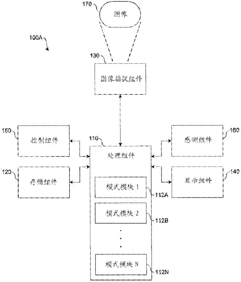
[0030] According to an embodiment of the present disclosure, Figure 1A A block diagram illustrating an infrared imaging system 100A for capturing and processing infrared images is shown. Infrared imaging system 100A includes processing component 110 , storage component 120 , image capture component 130 , display component 140 , control component 150 , and optionally, sensing component 160 .

[0031] In various implementations, infrared imaging system 100A may represent an infrared imaging device, such as an infrared camera, to capture one or more images, such as image 170 . Infrared imaging system 100A may represent any type of infrared camera that, for example, detects infrared radiation and provides representative data (eg, one or more snapshots or video infrared images). For example, infrared imaging system 100A may represent an infrared camera for the near, mid, and / or far infrared spectrum. Infrared imaging system 100A may comprise a portable device and, for example, m...


PUM


Abstract

Systems and methods disclosed herein provide for infrared camera systems and methods for dual sensor applications. For example, in one embodiment, an enhanced vision system includes a visible light sensor adapted to capture a visible light image. The system also includes an infrared sensor adapted to capture an infrared image. The system also includes a processing component adapted to extract a luminance part from the captured visible light image, extract a luminance part from the captured infrared image, scale the luminance parts, and merge the scaled luminance parts to generate an output image. The system also includes a display component adapted to display the output image.

Description

technical field [0001] The present disclosure relates to infrared imaging systems, and more particularly, to infrared camera systems and methods for dual sensor applications. Background technique [0002] Utilize visible light cameras in a variety of imaging applications to capture color or monochrome images. For example, visible light cameras are typically utilized for daytime applications in ambient light. [0003] Infrared cameras are utilized in various imaging applications to capture thermal emissions from objects as infrared images, and thus, the infrared cameras may not depend on ambient lighting. For example, infrared cameras may be utilized for nighttime applications to improve visibility in low light conditions that typically affect cameras limited to the visible spectral band. [0004] However, there are several drawbacks to traditional nighttime implementations for visible and infrared cameras. For example, a vehicle operator may have to alternate between disp...

Claims


Application Information

Patent Timeline
IPC IPC(8): H04N5/33
CPCH04N7/181H04N5/332H04N5/33H04N23/11
Inventor N.霍加斯滕J.S.斯科特P.B.理查森J.D.弗兰克A.A.理查兹J.T.乌拉维
Owner FLIR SYST INC
Why Eureka
Try Eureka