Eureka AIR delivers breakthrough ideas for toughest innovation challenges, trusted by R&D personnel around the world.

Tractor

A tractor and gear technology, applied in the field of tractors, can solve the problems of high manufacturing cost, high manufacturing difficulty, and high raw material cost, and achieve the effect of easy manufacturing, simple structure, and reliable quality

Inactive Publication Date: 2012-06-13
ZHEJIANG ZHICHENG ELECTRONICS TECH
View PDF6 Cites 5 Cited by
  • Summary
  • Abstract
  • Description
  • Claims
  • Application Information

AI Technical Summary

Problems solved by technology

[0003] The shortcomings of the traction motor with this structure are: 1. The overall structure is complex; 2. The action produced by the electromagnetic iron-absorbing component will not be able to brake the damping block due to the cumulative manufacturing error of the tractor itself, and the traction force will not be able to slide back halfway. Phenomenon; 3) The planetary gear assembly in the transmission gear assembly has a complex structure and many parts, which makes it difficult to control the quality; 4) The cost of raw materials is high and the manufacturing cost is high
[0005] The disadvantage of this type of retractor is that the structure is complex. The magnetic ring, copper ring, and tension spring that replace the electromagnetic iron-absorbing part have a force ratio relationship that is difficult to control, and the quality is extremely unstable. Due to the high manufacturing difficulty, it increases manpower. Cost and equipment cost, so it also increases the cost of the product

Method used


Image

  • Tractor
  • Tractor
  • Tractor

Examples


Embodiment

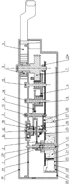
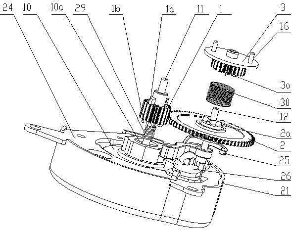
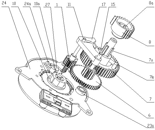
[0033] Such as figure 2As shown, the present invention separates the rotor magnetic steel 10 of the synchronous motor from the central gear 1, and sets a cross-toothed structure separated up and down. After meshing, the central gear 1 drives the set reduction gear assembly. Between the 3, a cross-toothed structure is similarly arranged. Properly increase the height of the tooth part of the central gear, so that the tooth part of the central gear 1 is always meshed with the tooth part of the gear 2, so that the two separation and meshing structures can be connected in series, which plays a key role in traction start, traction maintenance and traction recovery. Easy controls. Such as Figure 9 As shown, due to the simple control device designed above, the rest of the reduction gear assembly uses ordinary gears 4 and 5 to replace the original complex reduction assembly mainly composed of planetary gears, making the tractor structure simpler and more reasonable .

[0034] The...


PUM


Abstract

The invention discloses a tractor, which comprises a tractor shell. A synchronous motor and a speed reduction gear set are arranged in the tractor shell, the synchronous motor comprises a stator part and a rotor part, the stator part comprises an upper motor cover, a motor shell and a coil frame, the rotor part comprises magnetic steel arranged between the upper motor cover and the motor shell, acenter shaft is arranged at the center of the magnetic steel, and a center gear is arranged on the center shaft above the motor shell. The speed reduction gear set comprises a first gear and a secondgear, a slope separator for controlling vertical moving of the center gear is arranged on the center shaft, the magnetic steel and the center gear are provided with cross-tooth structures which are matched to each other, a center spring is arranged between the magnetic steel and the center steel, both the first gear and the second gear are provided with cross-tooth structure which are matched to each other, and a gear spring is arranged between the first gear and the second gear. The center gear and the first gear always mesh to each other when respectively move.

Description

technical field [0001] The invention relates to a traction device in the field of automatic switch and control of automatic water, gas and valves, in particular to a traction device with simple structure and stable quality. Background technique [0002] At present, there are roughly two types of tractors on the market, one structure, the gear box body is composed of upper and lower shells, a central fixing frame is built in the box body, and a synchronous motor is installed in the lower casing below the central fixing frame , the pole plate of the synchronous motor is fixed with a shaft for the gear to run, and a group of gear components that increase the torque by slowing down the speed are mounted on the shaft, and an electromagnetic iron-absorbing component is vertically installed on the pole plate of the synchronous motor. The rear synchronous motor and the electromagnetic magnet work at the same time, the synchronous motor drives the gears to run, the electromagnetic ma...

Claims


Application Information

Patent Timeline
Patent Type & Authority Applications(China)
IPC IPC(8): H02K7/116
Inventor 于佳泉
Owner ZHEJIANG ZHICHENG ELECTRONICS TECH
Why Eureka
Eureka Blog
Learn More