Fixed-gain self-excited non-contact resonant converter and control method thereof

A resonant converter and resonant conversion technology, which is applied in the direction of control/regulation system, DC power input conversion to DC power output, instruments, etc., to achieve the effect of output stability

Inactive Publication Date: 2012-06-27
NANJING UNIV OF AERONAUTICS & ASTRONAUTICS
View PDF0 Cites 33 Cited by
  • Summary
  • Abstract
  • Description
  • Claims
  • Application Information

AI Technical Summary

Problems solved by technology

To overcome the above-mentioned shortcomings of the existing non-contact converter external control method that is not conducive to quick response to the parameter change of the converter, combined with the advantages of simple self-excited control and quick response to the change of the converter parameter, a new method suitable for non-contact po

Method used


Image

  • Fixed-gain self-excited non-contact resonant converter and control method thereof
  • Fixed-gain self-excited non-contact resonant converter and control method thereof
  • Fixed-gain self-excited non-contact resonant converter and control method thereof

Examples


Embodiment 1

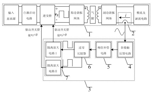
[0033] attached figure 1 Shown is the structural block diagram of the fixed-gain self-excited non-contact resonant converter, which includes a non-contact resonant converter, current signal detection and drive circuit.

[0034] First of all, the theoretical basis of the control strategy in the present invention is explained in conjunction with the circuit: the characteristic that the measured current on the secondary side at the fixed gain of the non-contact resonant converter is in phase with the square wave signal at the midpoint of the inverter bridge arm in the main circuit

[0035] When the rectifier bridge is continuously turned on, no matter which compensation method is used, the voltage and current at the midpoint of the bridge arm are always in the same phase, so the secondary rectifier bridge, filter link and load can be equivalent to a linear resistor R E , and then substituting the leakage inductance model of the non-contact transformer, the fundamental equivalent...

Embodiment 2

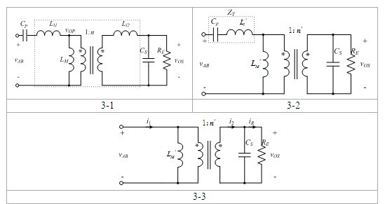
[0050] attached Figure 5 It is an embodiment of a fixed-gain self-excited non-contact resonant converter, wherein the inverter bridge of the non-contact resonant converter adopts a full-bridge converter topology, and the primary / secondary side resonant network adopts series / series compensation. It is characterized in that, when using series / series compensation, by detecting the secondary side current of the non-contact transformer i 2 Form the driving signal of the full-bridge switch tube to ensure i 2 Output square wave signal with inverter bridge v S Completely in the same phase, so that the converter works at the intersection of the output voltage gain and the load-independent gain; and uses the self-excited control method to respond to the transformation of the transformer parameters in real time. attached Figure 6 And attached Figure 7 respectively k max =0.528, k min=0.253, the experimental waveforms under different load conditions; attached Figure 8 is t...

Embodiment 3

[0052] attached Figure 9 Another embodiment of the fixed-gain self-excited non-contact resonant converter, wherein the primary / secondary resonant network adopts series / parallel compensation. It is characterized in that, when using series / parallel compensation, by detecting the input current of the rectifier bridge i R Form the driving signal of the full-bridge switch tube to ensure i R Output square wave signal with inverter bridge v S Completely in phase, so that the converter works at the intersection of the output voltage gain and the load-independent gain; and uses the self-excited control method to respond to the transformation of the transformer parameters in real time. attached Figure 10 And attached Figure 11 respectively k max =0.528, k min =0.253, the experimental waveforms under different load conditions; attached Figure 12 is the load regulation under the two coupling coefficients. It can be seen that the converter is always self-excited and works ...


PUM


Abstract

The invention discloses a fixed-gain self-excited non-contact resonant converter and a control method thereof, belonging to the field of electric energy conversion. The fixed-gain self-excited non-contact resonant converter comprises a self-excited non-contact resonant converter main circuit, a secondary side current detection circuit and a driving signal generation circuit. Detected current is set according to the compensation method of a resonant converter: for series/series and parallel/series compensation circuits, the secondary side current of a non-contact transformer is detected, and for series/parallel compensation circuits, the input current of a secondary side rectifier bridge is detected. The detected current is detected by the secondary side current detection circuit, a detection signal is isolated and fed back to a primary side through the driving signal generation circuit, and phase compensation is conducted to accurately detect the phase information of the secondary side detected current. According to a found characteristic that the phase of the secondary side detected current at the fixed gain position of the non-contact resonant converter is the same as the phase of square wave signals at the middle point of an inverter bridge arm in the main circuit (1), the detected secondary side current signals are converted into the driving signals of the main circuit to realize self-excitation control. On one hand, a real-time response can be made to the parameter change of the non-contact transformer; and on the other hand, the output of the non-contact resonant converter can be ensured to be stable when a load is changed.

Description

technical field [0001] The invention relates to a fixed-gain self-excited non-contact resonant converter suitable for a non-contact electric energy transmission system and a control method thereof, belonging to the field of electric energy conversion. Background technique [0002] Non-contact power supply is a new type of power transmission mode based on magnetic field coupling to realize "wireless power supply". The non-contact transformer with completely separated primary and secondary sides is used to transmit power through the coupling of high-frequency magnetic field, so that the power supply side and the power consumption side are seamless during the energy transfer process. physical connection. Compared with the traditional contact power supply, non-contact power supply is convenient and safe to use, without sparks and electric shock hazards, without dust accumulation and contact loss, without mechanical wear and corresponding maintenance problems, and can adapt to a ...

Claims


Application Information

Patent Timeline
IPC IPC(8): H02M3/338H02J17/00H02J50/00H02J50/12
CPCY02B70/1433Y02B70/10
Inventor 陈乾宏曹玲玲任小永阮新波
Owner NANJING UNIV OF AERONAUTICS & ASTRONAUTICS
Why Eureka
Try Eureka