Labor-saving bicycle
A bicycle and flywheel technology, which is applied in the field of rickshaws, can solve the problem of inconvenient effort when pedaling and driving, and achieve the effect of good labor-saving effect.
- Summary
- Abstract
- Description
- Claims
- Application Information
AI Technical Summary
Problems solved by technology
Method used
Image

Examples
Embodiment Construction
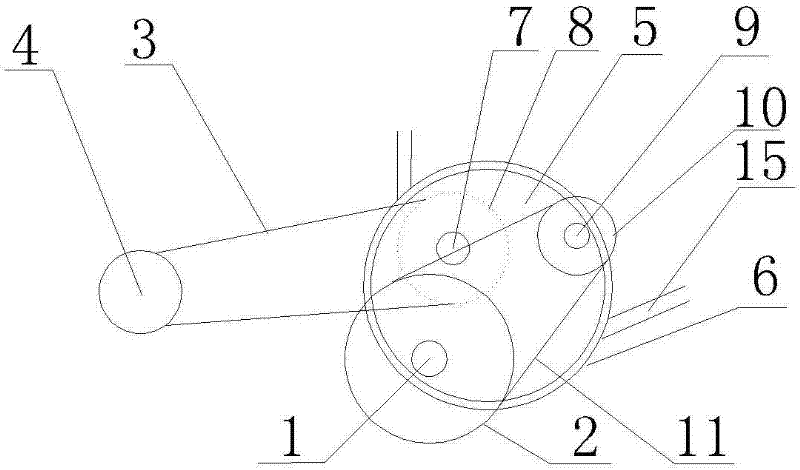
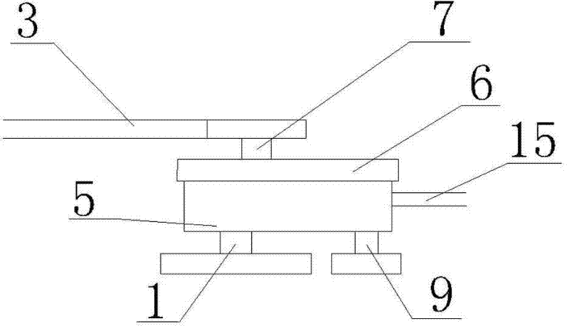
[0012] Such as figure 1 and figure 2 As shown, a labor-saving bicycle includes a pedal axis 1, a tooth plate 2, a chain I3, a rear axle 4, a box body 5 and a box body shell 6, and is characterized in that: the box body 5 is also provided with an output shaft 7, Flywheel Ⅰ 8, input shaft 9, flywheel Ⅱ 10, chain Ⅱ 11 and transmission assembly 12, output shaft 7 has flywheel Ⅰ 8, input shaft 9 has flywheel Ⅱ 10, pedal center shaft 1 is linked with input shaft 9 through chain Ⅱ 11, and input shaft 9 is linked with the output shaft 7 through the transmission assembly 12.
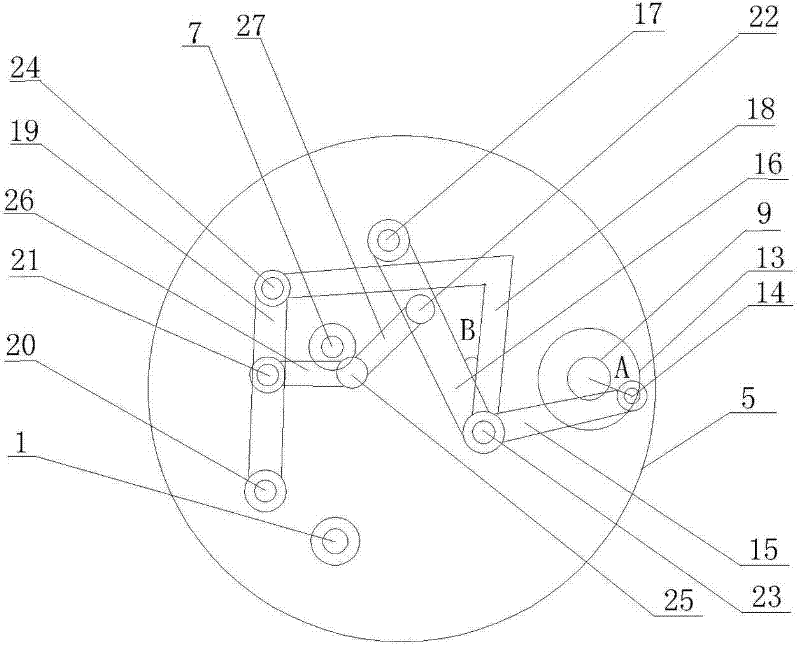
[0013] Such as image 3 As shown, the structure of the transmission assembly 12 is: there is a disc 13 on the input shaft 9, and a rotating shaft I14 on the disc 13. The rotating shaft I14 is connected to the movable shaft III23 through the transmission rod I15, and the movable shaft III23 is connected to the fixed shaft through the rod II16. I17 is connected, the fixed shaft I17 is fixed on the box body 5, o...
PUM
 Abstract
Description
Claims
Application Information
PatSnap Eureka turns technology decisions into work you can execute. Powered by our Innovation Knowledge Graph, it runs expert workflows across engineering, life sciences, materials and intellectual property. Get your review-ready output in minutes.


