Plasma gasification refuse disposal method and device

A garbage treatment device, plasma technology, applied in the direction of solid waste removal, etc., can solve the problems of long reaction time, difficulty, limited processing capacity, etc.

Active Publication Date: 2012-07-11
北京光耀环境科技有限公司
View PDF10 Cites 14 Cited by
  • Summary
  • Abstract
  • Description
  • Claims
  • Application Information

AI Technical Summary

Problems solved by technology

The problem with this method is that the feeding is not uniform, there will be bias flow, nodulation, and difficulty in discharging the molten slag.
Long response time, limited throughput

Method used


Image

  • Plasma gasification refuse disposal method and device
  • Plasma gasification refuse disposal method and device
  • Plasma gasification refuse disposal method and device

Examples


Embodiment 1

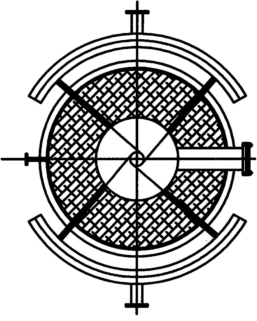
[0055] Air supply: The pyrolysis air supply of the present invention directly adopts industrial oxygen, because the oxygen content in the air is about 21%, which can effectively reduce the gas volume of the pyrolysis gas and improve the purity of the pyrolysis gas. The air supply pipe 8 is arranged in a circular shape cut at four corners, divided into upper and lower layers, and forms an angle of 20 to 30° downward with the plane where it is located, so that the gas in the furnace rises spirally, increasing the residence time and disturbance, and reducing the temperature of the pyrolysis gas. It has a good promoting effect on the formation of tar particles and the reduction of tar particles. The air supply speed is controlled at 40-60m / s, which has a strong penetrating power, which can make the material contact with oxygen well and improve the pyrolysis efficiency. Each air supply official road is equipped with a separate regulating valve, which can adjust the air pressure and...

Embodiment 2

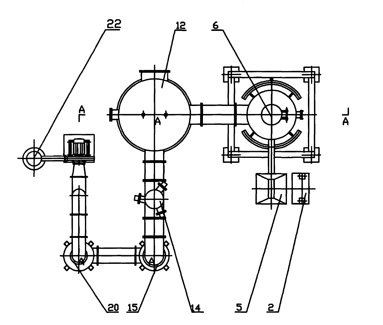
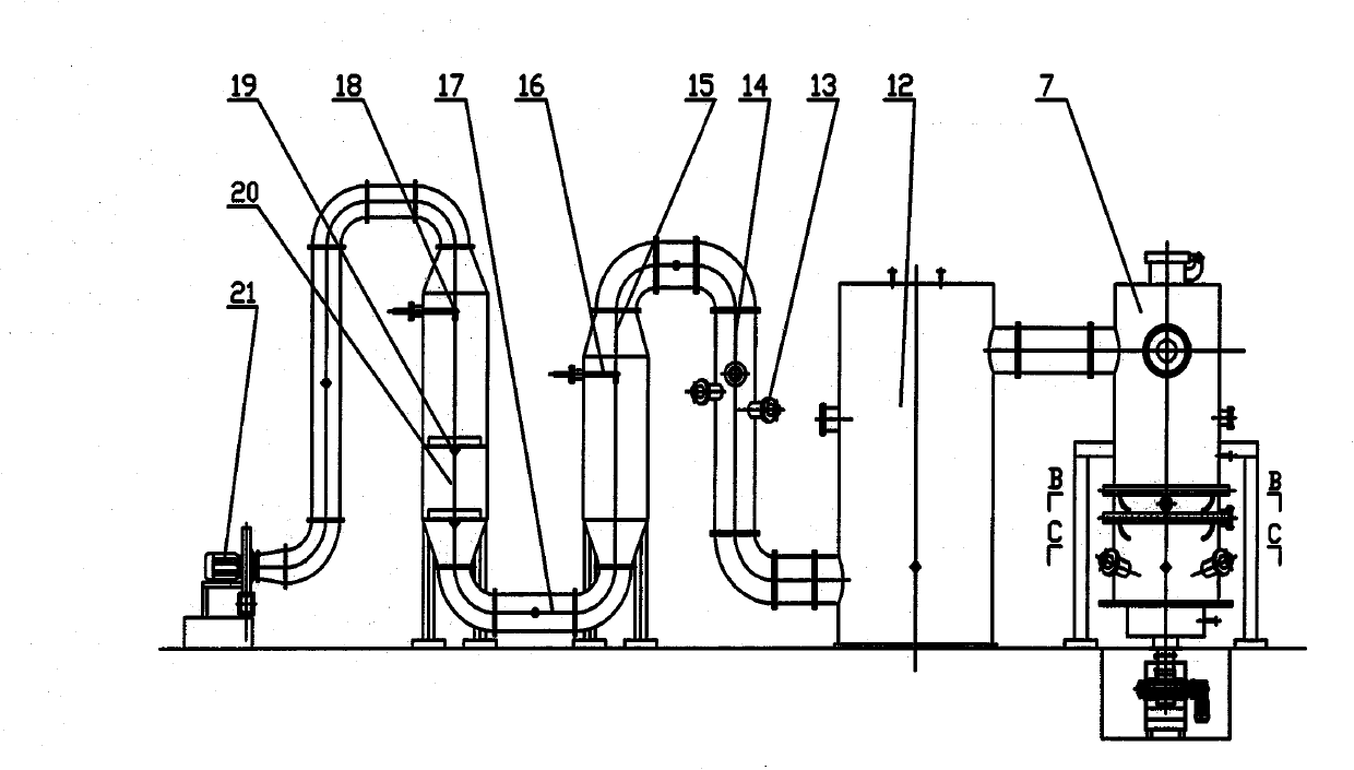
[0063] Position selection of the secondary gasification plasma torch: The secondary gasification plasma torch can be arranged in two positions, which can be arranged in the middle of the expansion reaction chamber 12 or in the vertical gas channel 14 . Adjust the number and power of the plasma torch according to the different requirements for the quality of the gas produced.

Embodiment 3

[0065] Selection of the position of the air supply device: the air supply pipe 8 can be arranged above the plasma torch of the gasification furnace 7, or arranged according to the position of the secondary gasification plasma torch. When the secondary gasification plasma torch is arranged in the expansion reaction chamber 12, The air supply pipe 8 is arranged under the plasma torch of the expansion reaction chamber 12 , and when the secondary gasification plasma torch is arranged in the vertical air passage 14 , the air supply pipe 8 is arranged under the plasma torch in the vertical air passage 14 . Choose different positions and air volumes according to the material composition and gas quality.


PUM


Abstract

The invention discloses a plasma gasification refuse disposal method and a device, comprising a pyrolysis gasification unit, a quench tower and a turbulent tower. A pyrolysis gasification furnace, an expansion reaction chamber, the quench tower and the turbulent tower are sequentially connected by a channel to form a vertically-alternate curve manifold gas channel. More than two of alternating-current plasma torches are arranged on the wall of the pyrolysis gasification furnace, and an air supply pipe is arranged on the alternating-current plasma torch. The axial lines of the alternating-current plasma torches are tangent with concentric circle taking the axial line of the pyrolysis gasification furnace as the center; a low-power alternating-current plasma torch is arranged on at least one of the expansion reaction chamber or the gas channel of the expansion reaction chamber and the quench tower to perform secondary pyrolysis. The quench tower is used for cooling gas, and the turbulent tower is used for desulfurizing and purifying gas. The invention uses the plasma technology to perform industrial gasification to the municipal solid waste so as to obtain usable gas; and the emission can achieve the environmental standards.

Description

technical field [0001] The invention relates to a method and a device for treating municipal domestic garbage. In particular, the invention relates to a method and device for industrialized gasification treatment of municipal solid waste by using plasma technology to obtain usable gas whose emission meets environmental protection standards. Background technique [0002] The basic principles of domestic waste disposal are harmlessness, reduction and recycling. The most suitable thing for waste incineration technology to deal with these principles is its excellent reduction effect. Usually, waste incineration technology can reduce the weight of domestic waste by 80% and volume reduction by more than 90%. is of great significance. [0003] The harmless effect achieved by waste incineration has also been widely recognized. At present, it is easy to be questioned because its gas may contain highly toxic organic substances such as dioxins that are difficult to control. But in ...

Claims


Application Information

Patent Timeline
Patent Type & Authority Applications(China)
IPC IPC(8): B09B3/00
Inventor 赵虎军孟繁磊
Owner 北京光耀环境科技有限公司
Why Eureka
Try Eureka