
Image forming device

An image and developing device technology, which is applied to the electrical recording process using charge graphics, equipment and instruments using the electrical recording process using charge graphics, and can solve the problem of handling cartridges, saving space, and increasing height. , Difficulty in use and other problems, to achieve good operability and setup

Inactive Publication Date: 2014-11-26
RICOH KK
View PDF10 Cites 0 Cited by
  • Summary
  • Abstract
  • Description
  • Claims
  • Application Information

AI Technical Summary

Problems solved by technology

However, in order to increase the opening angle of the arm member 60, a space for taking out the adjacent process cartridge 50 is required, so that the distance (interval) between the photosensitive drums 53 must be increased.
That is, there will be a problem that the operability and space saving of the process cartridge cannot be solved at the same time.
[0010] In addition, in the technique disclosed in Patent Document 2, since a plurality of image bearing members are arranged in the vertical direction, the height of the device increases, which causes a problem of installation. In addition, the most frequently used developer The replacement of the cartridge is inserted into the device from the horizontal direction, so the developer cartridge must be pulled out from the device in the horizontal direction and then pulled out in the vertical direction, resulting in poor operability
[0011] In addition, in the technology disclosed in Patent Document 3, although the height of the device can be reduced, since the cover must be opened in the vertical direction, there must be enough space above if the device is placed on a shelf. The problem becomes difficult. In addition, since the shape of the developer cartridge must be guided according to the rotation track of the upper cover, there is a problem that there is also a restriction in the position of the fulcrum of the upper cover rotation.
[0012] In addition, in the technology disclosed in Patent Document 4, it is necessary to secure a sufficient amount of drawing in the direction in which the assembly is pulled out from the device, and since the photoreceptor is pulled out from the device in the axial direction, there is a problem in paper jams. When it is necessary to operate the inside of the device from another surface, it will lead to a problem of reduced operability.
[0013] Therefore, in the technologies described in Patent Documents 1 to 4, there are problems that the miniaturization of the device (especially in the height direction), operability and installation performance cannot be satisfied at the same time.

Method used


Image

  • Image forming device
  • Image forming device
  • Image forming device

Examples


no. 1 approach

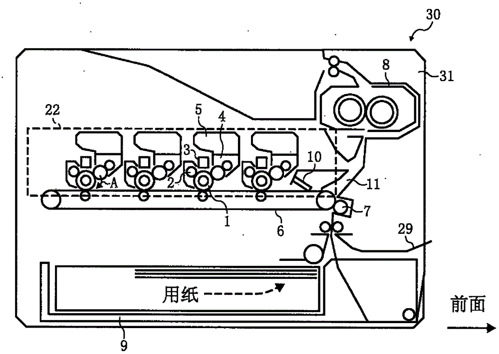
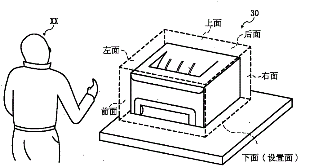
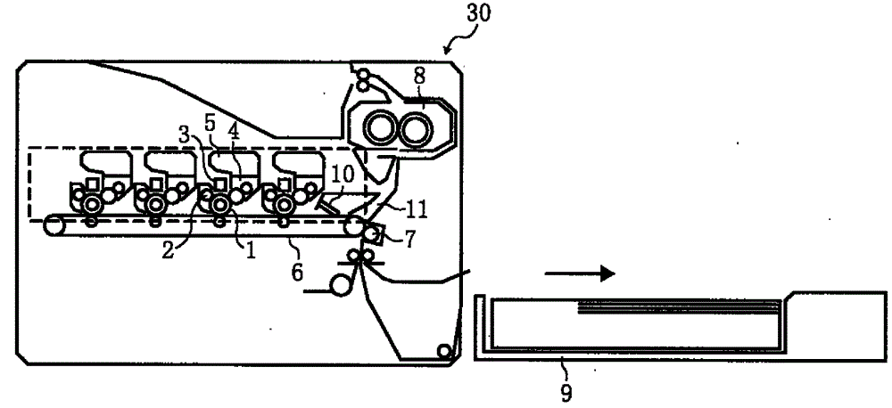
[0087] First, refer to figure 1 , figure 2 to explain the composition.

[0088] Such as figure 1 As shown, the image forming apparatus 30 includes: a plurality of cylindrical photoreceptors 1 (image carriers) rotating in the direction of arrow A (clockwise), and a charging device for charging the surface of the photoreceptors 1 2. Expose the surface of the charged photoreceptor 1 according to the image information, and then the LED3 of the light source that forms an electrostatic latent image on the photoreceptor 1 develops the electrostatic latent image on the photoreceptor 1 with toner (developer) Afterwards, a developing device 4 that forms a toner image on the photoreceptor 1, a developer cartridge 5 that accommodates the developer disposed above the developing device 4, and a toner image on a plurality of photoreceptors 1 The overlapping ring-shaped intermediate transfer body 6, the secondary transfer device 7 for transferring the toner image on the intermediate trans...

no. 2 approach

[0132] refer to Figure 11 Figure 13 , the image forming apparatus according to the second embodiment of the present invention will be described. In addition, the same code|symbol is attached|subjected to the same structure as 1st Embodiment, and the description is abbreviate|omitted.

[0133] Such as Figure 11 As shown, the photoreceptor supporting member 21 can set the axis of the photoreceptor 1 at a predetermined angle (the angle from the inclined position indicated by the solid line of the photoreceptor supporting member 21 in the figure to the vertical position indicated by the dotted line). Center to rotate.

[0134] by Figure 11 When describing the action when installing the photoreceptor 1, the photoreceptor 1 that is not installed is removed from the supporting member opening 23 (refer to Figure 9 ) is inserted until the support member 22 and the photoreceptor support member 21 meet.

[0135] The position determining part of the supporting member 22 and the p...


PUM


Abstract

The invention provides a miniaturized image forming device which has good operation and setting performance. The image forming device comprises a plurality of photoreceptors (1) parallelly arranged in a parallel surface, an LED (3) close to the photoreceptors (1), a developing unit (4), a developer card box (5), an intermediate transfer body (6), a fusing unit (8), a support photoreceptor, a support member (22) of the developing unit (4) and the LED (3) which is freely pulled out from a device body in a horizontal direction perpendicular to an axial direction of the photoreceptors (1), a paper plate (9) for carrying paper, a paper carrying path (11) which can freely open in one side of a pulling out direction of the support member (22) of the device body and a support body opening part which is arranged in the support member (22) to detach the photoreceptors (1) in an axial direction of the photoreceptors (1) generally perpendicular to the pulling out direction of the support member (22) relative to the support member (22) when the support member (22) is pulled out from the device body.

Description

technical field [0001] The present invention relates to an electrophotographic image forming apparatus in which a light source composed of LEDs or the like is arranged close to an image carrier such as a copying machine, a printer, or a facsimile. Background technique [0002] Electrophotographic image forming apparatuses such as copiers, printers, and facsimiles are required to be excellent in all aspects of apparatus miniaturization (especially in the height direction), operability (including maintenance work), and ease of installation. [0003] In an image forming apparatus, a light source composed of LEDs etc. arranged close to an image carrier is designed so that it cannot be detached from the device body because maintenance such as replacement is basically not required, and in order to expose the image carrier with high precision However, it is necessary to arrange the light source close to the image carrier. Therefore, it is difficult to make the image carrier capable...

Claims


Application Information

Patent Timeline
Patent Type & Authority Patents(China)
IPC IPC(8): G03G15/00
Inventor 江藤拓哉松下诚
Owner RICOH KK
Learn More