Life buoy for water rescue

A lifebuoy and circle body technology, which is applied in water lifesaving, ships, ship safety, etc., can solve problems such as inconvenient use of lifebuoys

A lifebuoy and circle body technology, which is applied in water lifesaving, ships, ship safety, etc., can solve problems such as inconvenient use of lifebuoys

CN102700693AInactive Publication Date: 2012-10-03SHANGHAI QIBAO HIGH SCHOOL

Image

  • Life buoy for water rescue
  • Life buoy for water rescue
  • Life buoy for water rescue

Examples


Embodiment Construction

[0018] Below in conjunction with accompanying drawing, the present invention is described in further detail, so that those skilled in the art understand:

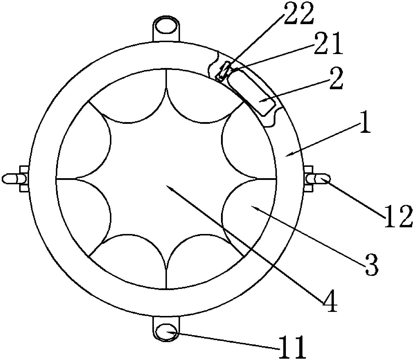
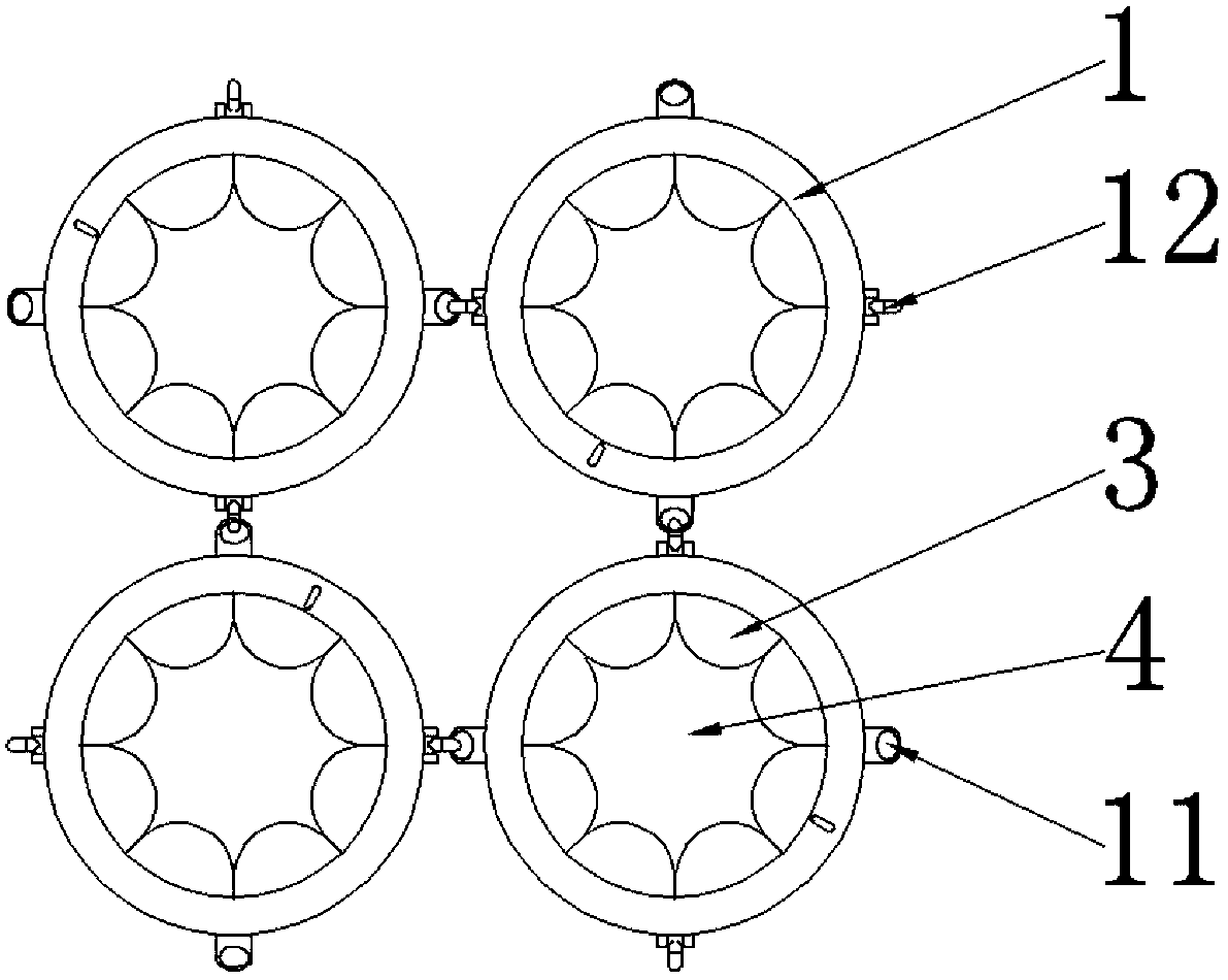
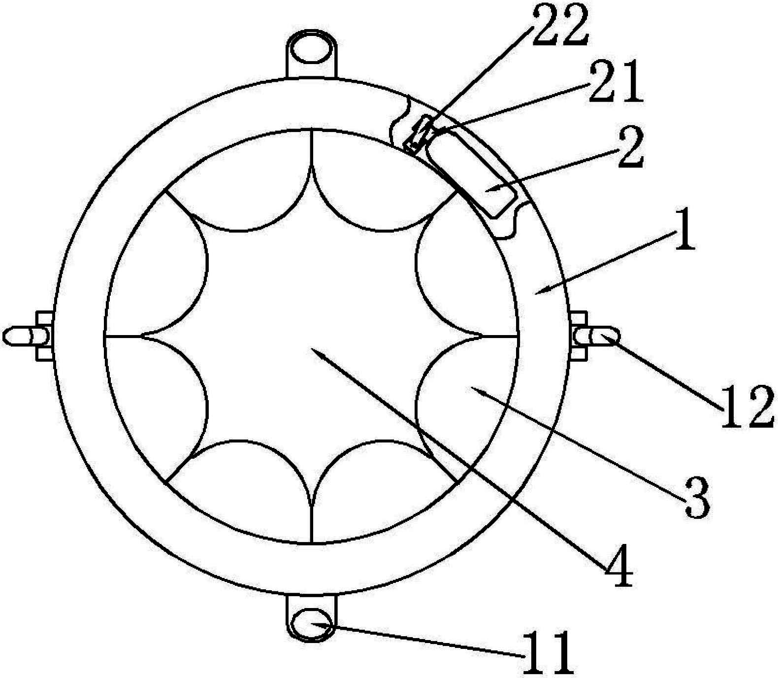
[0019] Such as Figure 1-2 As shown, the labels respectively represent: ring body 1, steel ring 11, buckle ring 12, high-pressure gas cylinder 2, manual valve 21, valve stem 22, air bag 3, annular portion 4.

[0020] see figure 1 As shown, the life buoy for water rescue provided in this embodiment includes an annular ring body 1, and eight airbags 3 are arranged on the inner edge of the ring body 1, and the airbags 3 are sequentially arranged along the inner edge of the ring body 1. Continuously and evenly distributed, and communicated with each other, one of the airbags 3 is provided with a vent hole 31 blocked by a plug. In addition, a high-pressure gas cylinder 2 is arranged in the ring body 1, and a manual valve 21 with a valve stem 22 is arranged on the high-pressure gas cylinder 2, and the exhaust hole of the manual...


PUM


Abstract

The invention relates to a water life saving device, in particular to a life buoy for water rescue. The life buoy comprises an annular ring body and is characterized by also comprising a high-pressure air cylinder and at least one air bag, wherein the air bag is arranged at the inner edge of the ring body; the air outlet of the high-pressure air cylinder is only connected to the air valve of the air bag; and the air bag is enclosed into an annular part for accommodating a human body after being expanded, or the air bag and the partial inner edge of the ring body are enclosed into the annular part for accommodating the human body. Compared with the prior art, the life buoy for the water rescue provided by the embodiment of the invention has the advantages that: the life buoy is more easily sleeved on the body of a drowning person and has a function of automatically fixing the drowning person; a plurality of life buoys can be mutually connected; and the life buoy is particularly suitable for rescuing when multiple persons fall into water.

Description

technical field [0001] The invention relates to a lifesaving device on water, in particular to a lifebuoy ring for water rescue. Background technique [0002] A lifebuoy is a kind of water lifesaving equipment, usually made of cork, foam plastic or other light materials with a small specific gravity. In the event of an accident on the water, the lifebuoy is often used to rescue those who fall into the water or to save themselves. Existing life buoy is in order to save people's physical strength, and the annular portion that accommodates human body in the middle is only designed to be slightly larger than human body, makes user's both arms need not open larger angle and just can be supported on the life buoy. And the structural design and the mode of use of this kind of survival buoy basically all are to rely on the self-rescue of the person who fell into the water, such as throwing the lifebuoy to the rescuer in the water, and the rescuer actively climbs to this lifebuoy to ...

Claims


Application Information

Patent Timeline
03 Oct 2012
Publication
CN102700693A
IPC
B63C9/15; B63C9/18
Inventors
高俊; 叶骁宇