A hydraulic descender

A descending device, hydraulic technology, applied in the direction of life-saving equipment, building rescue, etc., can solve problems such as difficulties, and achieve the effect of wide application prospects

Inactive Publication Date: 2014-10-29
HOHAI UNIV CHANGZHOU
View PDF3 Cites 1 Cited by
  • Summary
  • Abstract
  • Description
  • Claims
  • Application Information

AI Technical Summary

Problems solved by technology

The use of the existing descending device requires strong professional skills, and the descending speed needs to be adjusted and controlled by oneself. It needs a lot of training to be able to use it correctly. It is difficult for ordinary people to master the descending technology in a short time.

Method used


Image

  • A hydraulic descender
  • A hydraulic descender

Examples


Embodiment Construction

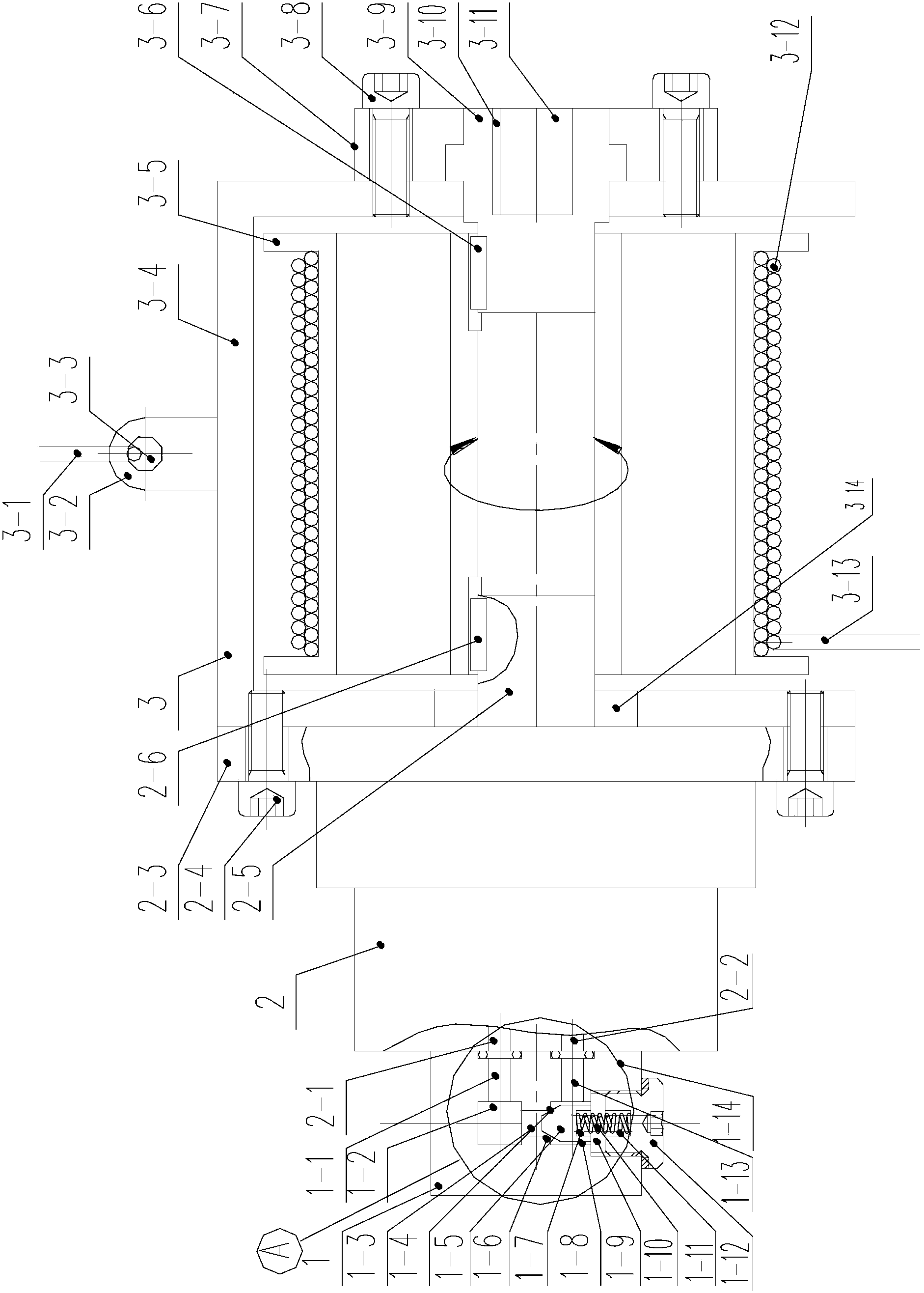
[0019] like figure 1 , figure 2 As shown, a hydraulic slow down device includes a one-way throttle valve group 1, a hydraulic pump 2 and a winch assembly 3;

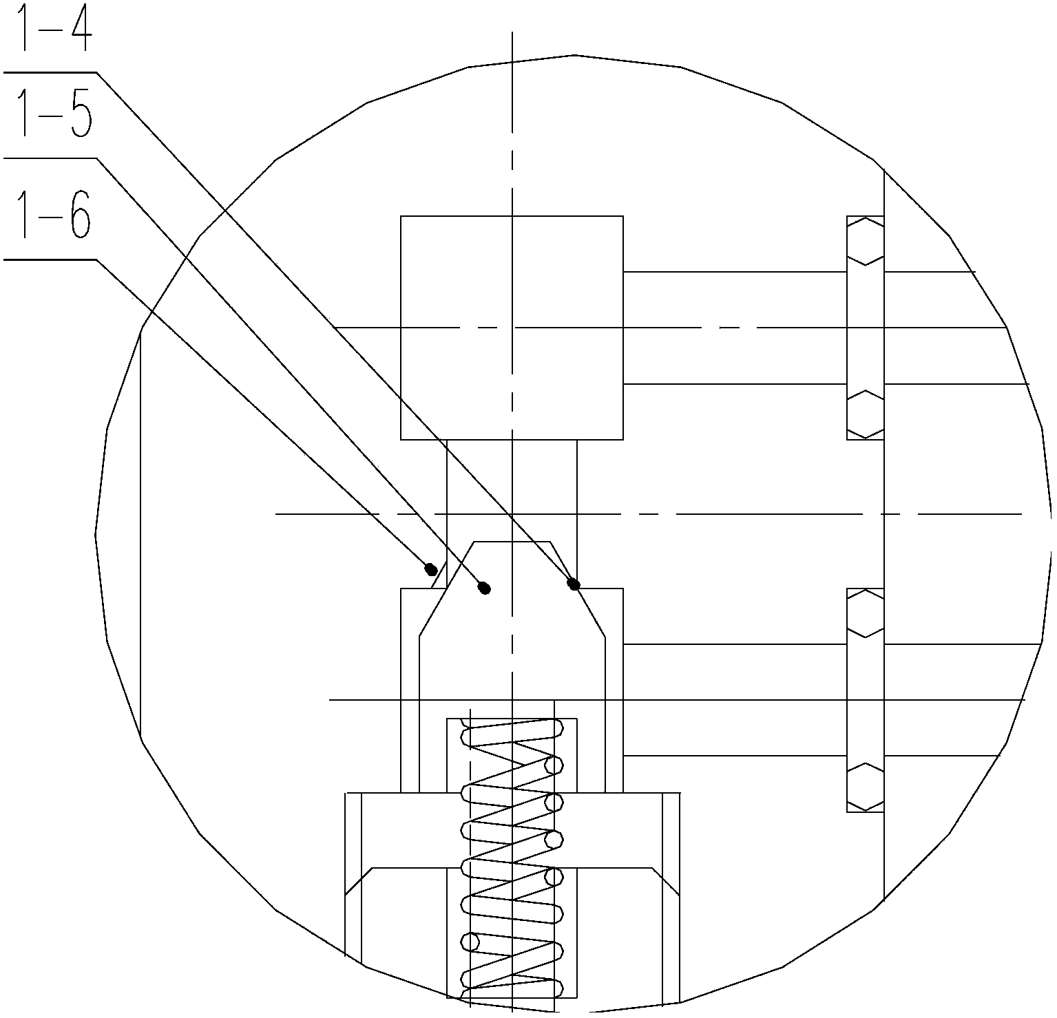
[0020] The one-way throttle valve group 1 includes a valve body 1-14, a one-way valve core 1-5, a spring 1-10 and a plug 1-12; the valve body 1-14 is provided with a valve group oil port 1-1, valve group upper oil chamber 1-2, valve group upper and lower connecting channels 1-3, valve group lower oil chamber 1-8, plug chamber 1-9 and valve group lower oil port 1-13; A one-way valve seat 1-4 is formed between the upper and lower connecting passages 1-3 of the valve group and the lower oil chamber 1-8 of the valve group, and an oil passage groove is opened on the circumference of the one-way valve seat 1-4—one-way Valve seat throttling groove 1-6, the upper part of the one-way valve seat throttling groove 1-6 passes through the upper and lower passages 1-3 of the valve group, the upper oil cavity 1-2 of the valve group ...


PUM


Abstract

The invention discloses a hydraulic descent control device which mainly comprises a one-way throttle valve bank, a hydraulic pump (or a hydraulic motor) and a reel component. The one-way throttle valve bank is fixedly mounted on the hydraulic pump, an upper oil port of the one-way throttle valve bank is communicated with an upper oil port of the hydraulic pump, and a lower oil port of the one-way throttle valve bank is communicated with a lower oil port of the hydraulic pump. A mounting flange of the hydraulic pump is connected with a reel frame of the reel component through a screw, an output shaft of the hydraulic pump is connected with one end of a reel through a key, and the other end of the reel is connected with a support shaft through a key. The reel frame can be connected with a fixing body through an upper fixing rope and a lug on the upper portion of the reel frame, and a rope on the reel is connected with a human body through a human body connecting rope at the lower end of the reel. The hydraulic descent control device can be used for realizing high-altitude stability and safe descent of a human body, particularly can play a great role in personnel rescue of high-rise buildings, and has a wide application prospect if serving as a fire fighting instrument.

Description

technical field [0001] The invention relates to a hydraulic descending device, in particular to a hydraulic descending device composed of a hydraulic pump, a one-way throttle valve group and a winch assembly. Background technique [0002] At present, high-rise buildings such as high-rise office buildings and residential buildings have been widely used. In the event of emergency events such as fires and earthquakes, it is necessary to adopt reasonable self-rescue and rescue methods. The common rescue method is to evacuate through rescue channels, or use Even so, casualties often occur in the above emergencies. Strengthening emergency handling and self-rescue can greatly reduce or even avoid major casualties. If high-rise buildings can be equipped with certain personnel self-rescue equipment, in the event of an emergency, more escape methods can be selected for self-rescue. For example, using a descending device to escape from a window, etc. The use of the existing descendin...

Claims


Application Information

Patent Timeline
Patent Type & Authority Patents(China)
IPC IPC(8): A62B1/12
Inventor 钱雪松钱子凡
Owner HOHAI UNIV CHANGZHOU
Why Eureka
Try Eureka