
Discharge gap device

A discharge gap and installation groove technology, applied in the direction of circuits, electrical components, insulators, etc., can solve the problems of unstable discharge voltage, poor arc extinguishing ability, easy arc burns on insulators, etc., and achieve stable arc starting voltage, convenient adjustment, and convenience The effect of the discharge gap distance

Inactive Publication Date: 2012-10-24
GULIFA GRP CO LTD +1
View PDF5 Cites 10 Cited by
  • Summary
  • Abstract
  • Description
  • Claims
  • Application Information

AI Technical Summary

Problems solved by technology

[0002] In order to improve the safety of the transmission line, reduce the flashover that occurs along the insulating surface during overvoltage, and the burn of the insulator surface caused by the flashover causes the insulation performance to decline, a voltage equalizing ring or an arc striking angle is often set at both ends of the insulator, and the arc striking angle is The cost is low, but the discharge voltage is unstable and the arc extinguishing ability is poor. If the circumference of the uniform ring is small, the discharge is easy to burn the insulator. If the circumference is large, the cost is high, and the dry arc distance between phases will be reduced if the circumference is too large.
And the traditional arc starting angle or uniform ring cannot meet the installation requirements applicable to porcelain insulators and composite insulators at the same time

Method used


Image

  • Discharge gap device
  • Discharge gap device
  • Discharge gap device

Examples


Embodiment Construction

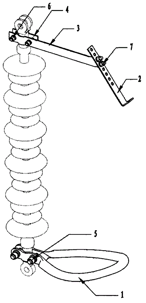
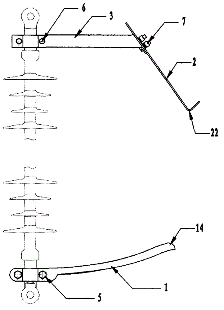
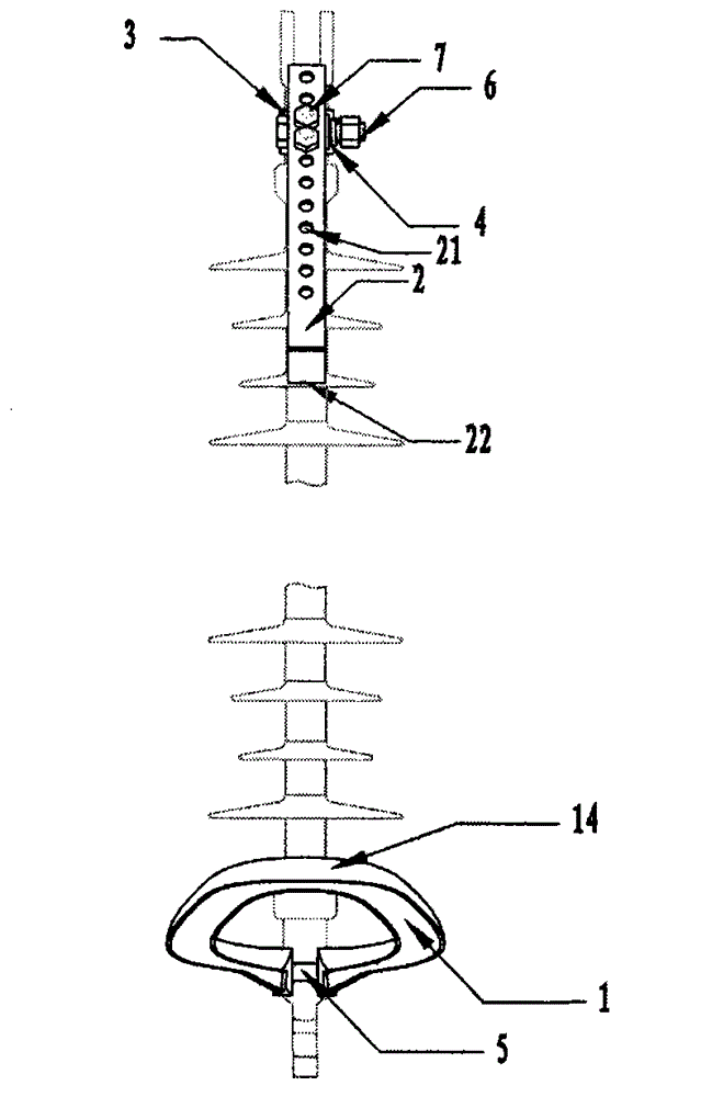
[0020] Depend on Figure 1-Figure 5 It can be seen that the discharge gap device of the present invention is mainly composed of a high-voltage arc striking ring 1, an arc striking angle 2, a fixing plate 3, a pressing plate 4, a first fastener 5, a second fastener 6 and a third fastener 7. The shape of the high-voltage arc-starting ring 1 is oval with one end open, and there are two parallel and opposite installation handles 11 at the opening, which are installed on the high-voltage end of the insulator under the action of the first fastener 5. The high-voltage arc-starting ring 1 The other end is a slightly upwardly bent arc striking end 14; one end of the fixed plate 3 and the pressure plate 4 are installed on the low-voltage end of the insulator through the second fastener 6, and the other end of the fixed plate 3 is provided with a double hole 33; The connecting end of the arcing angle 2 is provided with multiple joint holes 21, and two adjacent joint holes can be selected...


PUM


Abstract

The invention discloses a discharge gap device for preventing surface flashover of an insulator, which can solve the problem that the surface flashover of the insulator is cuased under the overvoltage to burn the insulator. The technical scheme of the invention is as follows: the discharge gap device comprises a high voltage arc initiating ring, an arcing horn, a pressing plate and a fastening piece; the high voltage arc initiating ring is arranged at a high voltage end of the insulator; a fixing plate and the pressing plate are arranged at a low voltage end of the insulator; and the arcing horn is connected with the fixing plate by the fastening piece, and the other end of the arcing horn bends downwards to form a discharge gap with the high voltage arc initiating ring. The discharge gap device not only can be directly fixed on fittings of two ends of a composite insulator, but also can be fixed on a cross yoke plate by installing holes to be connected with a ceramic insulator. The invention provides the novel discharge gap device adaptive to the composite insulator and the ceramic insulator and having rapidness in installation, adjustable gap, stable discharge voltage and good arc resistance and arc quenching performance.

Description

technical field [0001] The invention relates to an insulator protection device, which belongs to the field of electrical protection in power networks, in particular to a discharge gap device for preventing flashover on the surface of an insulator, which can solve the problem of burning the insulator due to flashover on the surface of the insulator under overvoltage. Background technique [0002] In order to improve the safety of the transmission line, reduce the flashover that occurs along the insulating surface during overvoltage, and the burn of the insulator surface caused by the flashover causes the insulation performance to decline, a voltage equalizing ring or an arc striking angle is often set at both ends of the insulator, and the arc striking angle is The cost is low, but the discharge voltage is unstable and the arc extinguishing ability is poor. If the circumference of the uniform ring is small, the arc will easily burn the insulator. If the circumference is large,...

Claims


Application Information

Patent Timeline
Patent Type & Authority Applications(China)
IPC IPC(8): H01B17/46H01B17/38
Inventor 刘明慧张启和刘勇龙王玉发郑哲
Owner GULIFA GRP CO LTD
Learn More