Eureka AIR delivers breakthrough ideas for toughest innovation challenges, trusted by R&D personnel around the world.

Discharging gap device

A discharge gap and installation slot technology, applied in the direction of circuits, electrical components, insulators, etc., can solve the problems of arc easy to burn insulators, unstable discharge voltage, low cost of arc ignition angle, etc., and achieve good arc resistance and arc extinguishing performance, discharge The effect of voltage stability, suppression of vibration and galloping

Inactive Publication Date: 2013-09-04
STATE GRID CORP OF CHINA +2
View PDF6 Cites 0 Cited by
  • Summary
  • Abstract
  • Description
  • Claims
  • Application Information

AI Technical Summary

Problems solved by technology

[0002] In order to improve the safety of the transmission line, reduce the flashover that occurs along the insulating surface during overvoltage, and the burn of the insulator surface caused by the flashover causes the insulation performance to decline, a voltage equalizing ring or an arc striking angle is often set at both ends of the insulator, and the arc striking angle is The cost is low, but the discharge voltage is unstable and the arc extinguishing ability is poor. If the circumference of the uniform ring is small, the discharge is easy to burn the insulator. If the circumference is large, the cost is high, and the dry arc distance between phases will be reduced if the circumference is too large.

Method used


Image

  • Discharging gap device
  • Discharging gap device
  • Discharging gap device

Examples


Embodiment Construction

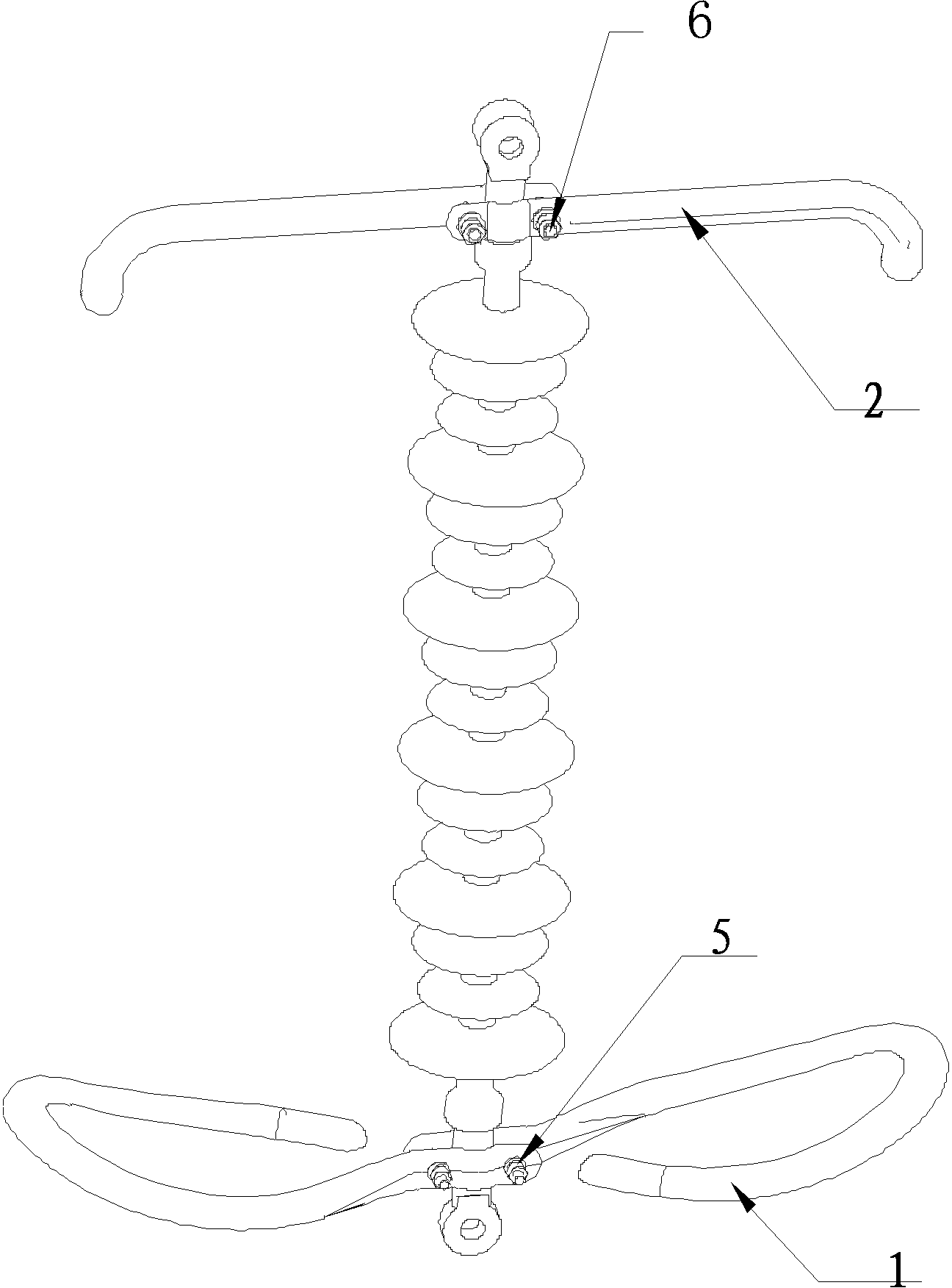
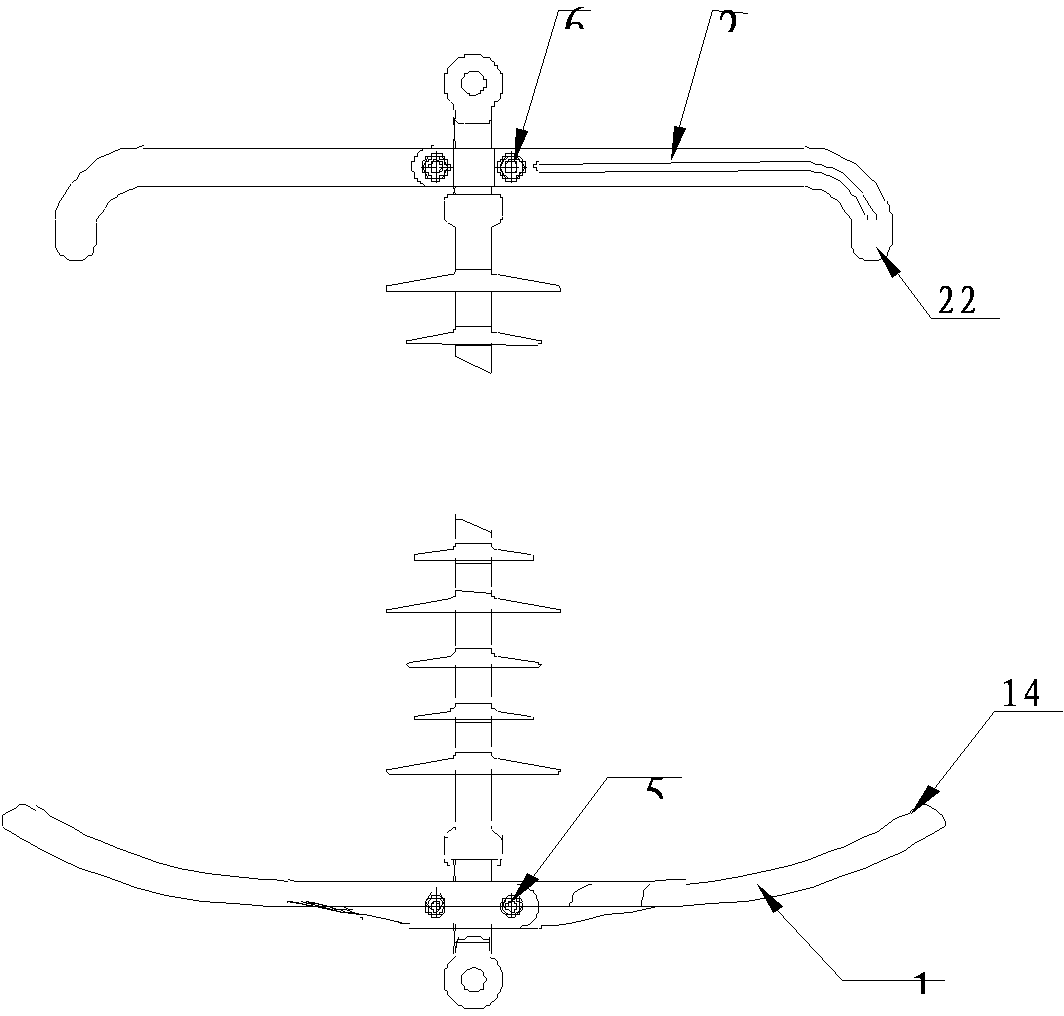
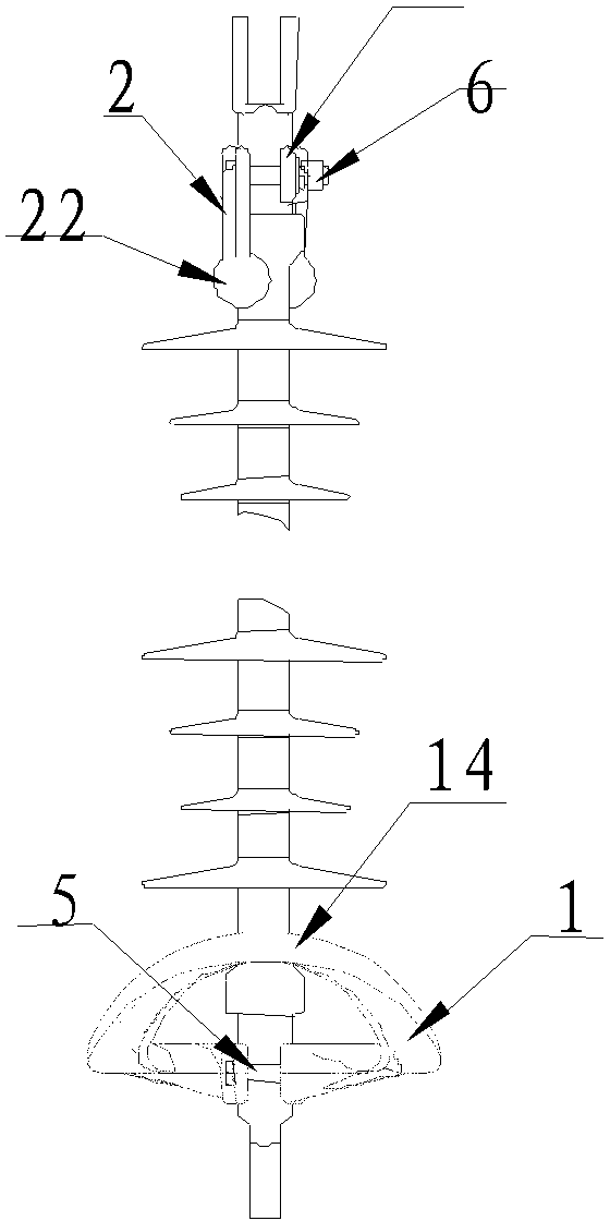
[0027] The present invention is a discharge gap device, such as Figure 1-Figure 4 As shown, the present invention is mainly composed of a high-voltage arc striking ring 1 , an arc striking angle 2 , a first fastener 5 and a second fastener 6 . It is symmetrically connected up and down on the two ends of the composite insulator by the high voltage arc striking ring 1 and the arc striking angle 2 . There are two high-voltage arc strike rings 1 symmetrically, connected by a first fastener 5 . There are two symmetrical arc striking angles 2 connected by second fasteners 6 .

[0028] Such as Figure 5 as shown, Figure 5 It is a schematic diagram of the structure of the medium and high voltage arc starting ring of the present invention. The shape of the high voltage arc starting ring 1 of the present invention is an open ellipse, one end of the opening is a mounting handle 11, and the other end of the oval shape of the high voltage arc starting ring 1 is a slightly upwardly cu...


PUM


Abstract

The invention relates to a discharging gap device which is an insulator protective device, belongs to the field of electric protection in a power grid, and particularly relates to the discharging gap device preventing the surface of an insulator from flashover. The discharging gap device is connected with fittings at the two ends of a compound insulator through high-voltage arc striking rings and arcing horns in an up-and-down symmetrical mode. Each high-voltage arc striking ring is designed to an oval with an opening, the two arc striking rings are horizontally and symmetrically installed, so that striking voltage is more stable, the electric arc principle is utilized to prevent the insulator from being burnt, and the interphase drying arcing distance is maintained. The two same arcing horns are horizontally and symmetrically installed, balls are utilized at the tail ends of the arcing horns to discharge, discharge times are increased, and the service life of a product is greatly prolonged. Compared with the prior art, the discharging gap device has the advantages of being suitable for the compound insulator, quick in installation, stable in discharging voltage, good in arc-resisting and arc extinguishing performance, long in service life, convenient to install, constant in grip strength, capable of restraining shaking and waving of wires, and free of damaging the wires and maintenance.

Description

technical field [0001] The invention relates to a discharge gap device, which is an insulator protection device, and belongs to the field of electrical protection in electric power networks, in particular to a discharge gap device for preventing flashover on the surface of insulators, which can solve the problem of burning insulators caused by flashover on the surface of insulators under overvoltage The problem. Background technique [0002] In order to improve the safety of the transmission line, reduce the flashover that occurs along the insulating surface during overvoltage, and the burn of the insulator surface caused by the flashover causes the insulation performance to decline, a voltage equalizing ring or an arc striking angle is often set at both ends of the insulator, and the arc striking angle is The cost is low, but the discharge voltage is unstable and the arc extinguishing ability is poor. If the circumference of the uniform ring is small, the arc will easily bu...

Claims


Application Information

Patent Timeline
IPC IPC(8): H01B17/46H01B17/38
Inventor 钟雅风耿莉娜韩洪刚程远朱义东杜彦强李冠华韦德福包蕊冯占稳杨璐羽
Owner STATE GRID CORP OF CHINA
Why Eureka
Eureka Blog
Learn More