A braced loop reactor

A loop reactor and brace technology, applied in the field of brace loop reactor, can solve the problems of poor resistance to toppling moment, increased investment cost, unfavorable energy saving and emission reduction, etc.

Active Publication Date: 2015-10-28
THE CHALLENGE PETROCHEM MACHINERY CORP
View PDF2 Cites 0 Cited by
  • Summary
  • Abstract
  • Description
  • Claims
  • Application Information

AI Technical Summary

Problems solved by technology

At present, the production capacity of a single polypropylene loop reactor in China has been increased from 70,000 tons / year domestically produced for the first time in 1996 to the current 400,000 tons / year. For tube reactors, since the sleeve adopts an integrated slender vertical structure, when the length of the sleeve exceeds 60m, the following disadvantages will occur: The installation method of the sleeve is only vertical and upright. If the increase exceeds 60m, it is difficult to guarantee the strength and stability of the high-rise steel structure under the action of dynamic load. If the strength and stability are improved only by increasing the wall thickness of the casing, not only the equipment investment cost will increase, but also the thickness of the thick wall will increase. Increased thermal resistance will have a negative impact on the heat transfer effect, which is not conducive to energy saving and emission reduction
[0006] For example, the Chinese invention patent application (publication number: CN101503483A) in the prior art disclosed an "improved environmental protection system" on August 12, 2009. A pumping device and method for slurry polymerization in a tube reactor", wherein the casing of the loop reactor involved is a vertical pipe section, which has poor stability and poor resistance to toppling moment, and cannot be applied to towering The structure meets its strength and stability requirements

Method used


Image

  • A braced loop reactor
  • A braced loop reactor
  • A braced loop reactor

Examples


Embodiment 1

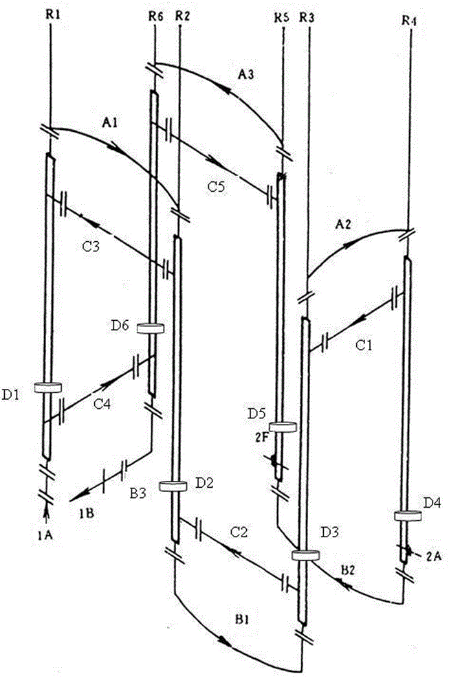
[0045] One of the specific implementations of a kind of diagonally braced loop reactor of the present invention, such as figure 2 and image 3 As shown, there are several bushings r1, r2, r3, r4, r5, r6, jacket connecting pipes, elbows a1, a2, a3, b1, b2, b3 and mounting supports d1, d2, d3, The casing includes an inner tube and an outer tube, and the elbow and the inner tube are sequentially connected in series to form a communication channel for conveying and reacting reaction materials. The outer pipe is connected, and the jacket flow channel formed between the inner pipe and the outer pipe is connected in series to form a communication flow channel for transporting cooling medium, wherein a is the reactant material flow inlet, and b is the reactant material flow outlet. The above technical features are the same as the structure of the loop reactor in the prior art. A diagonally braced loop reactor of the present invention also has other basic structures of the loop reac...

Embodiment 2

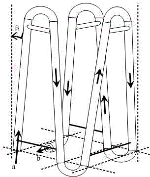
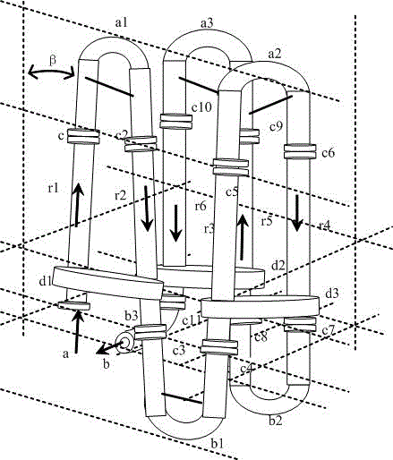
[0051] The second embodiment of a diagonally braced loop reactor of the present invention, as Figure 4 and Figure 5 As shown, the main technical solutions of this embodiment are the same as those of Embodiment 1, and the features not explained in this embodiment are explained in Embodiment 1, and will not be repeated here. The difference between this embodiment and Embodiment 1 is that the inclined casing includes an upper cylinder, a middle cylinder and a lower cylinder, at least one section of the upper cylinder, the middle cylinder and the lower cylinder is The cylinder is inclined, and the inclined installation angle β between the inclined cylinder and the vertical center line is set to 2°-10°.

[0052] Specifically, the inclined installation angles β of the inclined cylinders provided in the inclined sleeve are not equal.

[0053] Specifically, each section of cylinder is connected by butt flange or butt welding. c1, c2, c3, c4, c5, c6, c7, c8, c9, c10, c11, h1, h2 s...

Embodiment 3

[0055] The third specific embodiment of a diagonally braced loop reactor of the present invention, the main technical scheme of this embodiment is the same as that of embodiment 2, and the features not explained in this embodiment are explained in embodiment 2, No further details will be given here. The difference between this embodiment and embodiment 2 is: as Figure 4 As shown, the sleeves r1 and r2 are selected, wherein the upper cylinders r11 and r21 are inclined cylinders, the lower cylinders are inclined cylinders, and the middle cylinders r12 and r22 are vertical cylinders or inclined cylinders . in Figure 4 The lower cylinder is not shown in the figure. From the perspective of the upper cylinder r11 and r21 and the middle cylinder r12 and r22 of the combined casing r1 and r2, the distance between the lower ends of the middle cylinder r12 and r22 is greater than the distance between the upper ends of the upper cylinder r11 and r21 .


PUM


Abstract

The invention discloses a diagonal bracing type loop reactor which comprises multiple sleeves, a jacket communication pipe, a bend and a mounting support, wherein each sleeve comprises an inner pipe and an outer pipe; the bend and the inner pipes are sequentially connected in series to form a communication runner for the conveying and reaction of the reaction material; the jacket communication pipe is located at the bend and connected with the outer pipes; the jacket runners formed between the inner pipes and outer pipes are connected in series to form a communication runner for conveying the cooling medium; the sleeves include vertical sleeves and / or inclined sleeves; and the diagonal bracing type loop reactor is formed by combining the vertical sleeves and the inclined sleeves or by combining the inclined sleeves. Through the invention, the technical prejudice that the sleeves of the traditional loop reactor are vertical sleeves only is overcome; by adopting the improved technical scheme, the contact area of the mounting foundation can be increased so as to enhance the ability of the sleeves in resisting the toppling bending moment and disperse the load of the whole loop reactor at the same time; and the technology meets the requirements for the strength and stability of a high-rise structure.

Description

technical field [0001] The invention relates to the engineering technology of special mechanical equipment for petrochemical industry, in particular to a diagonally braced loop reactor. Background technique [0002] In the prior art, polyolefins (such as polypropylene and polyethylene) are the varieties with the largest output and consumption in general-purpose synthetic resins. The usual production techniques of polyolefins include three types: namely, slurry method, gas phase method and solution method . The so-called slurry method (Slurry Process), also known as slurry method or solvent method, is the earliest technology used to produce polypropylene in the world. The production technology of slurry method is the main method of producing HDPE. The production process method is: mixing propylene or ethylene with hydrocarbon solvent, and the produced polymer is suspended in the solvent. The industrial application of slurry method is earlier, and the process technology is ma...

Claims


Application Information

Patent Timeline
Patent Type & Authority Patents(China)
IPC IPC(8): B01J19/24
Inventor 陈孙艺
Owner THE CHALLENGE PETROCHEM MACHINERY CORP
Why Eureka
Try Eureka