
Novel mechanical grinding bar mechanism

A grinding rod and mechanical technology, applied in the direction of honing tools, etc., can solve the problems of accelerated aging of adhesives, high cost, and large heat.

Inactive Publication Date: 2012-12-19
韩士军
View PDF0 Cites 2 Cited by
  • Summary
  • Abstract
  • Description
  • Claims
  • Application Information

AI Technical Summary

Problems solved by technology

[0003] The purpose of the present invention is to provide a new type of mechanism for mechanical grinding rods, which overcomes the defects of large amount of adhesive, high cost, high heat, and accelerated aging of the adhesive in the current technology.

Method used


Image

  • Novel mechanical grinding bar mechanism

Examples


Embodiment Construction

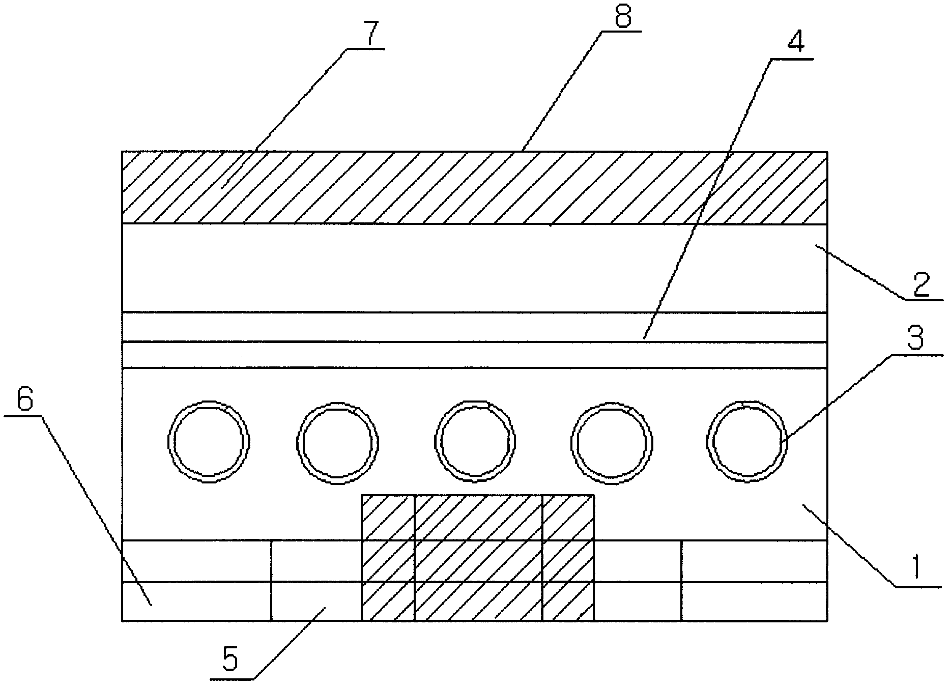
[0008] The structure of the grinding bar has a grinding bar 2, and a rubber strip 4 is installed on both sides of the grinding bar 2. The rubber bar 4 is fixed by a screw 3, and the grooves on the inner pressure plate 5, the outer pressure plate 6, and the grinding bar pressure plate 7 are connected with the grinding bar 2. The rubber strip 4 on the top is fastened to the oil stone seat 1 with the screw 3, and the grinding bar 2 is clamped on the oil stone seat 1 through the elastic change of the rubber strip 4, and then the oil seat body 8 is pressed on the top of the grinding bar 2, and the screw 3 Fasten.


PUM


Abstract

The invention discloses a novel mechanical grinding bar mechanism. A rubber strip is mounted in two sides of a grinding bar and fixed by using a bolt; grooves in an inner pressing plate, an outer pressing plate and a grinding bar pressing plate are fastened together with the rubber strip on the grinding bar by using bolts and an oil stone base; the grinding bar is clamped and pressed on the oil stone base through the elastic change of the rubber strip; and then, the oil stone base is pressed on the grinding bar and fastened by using a bolt.

Description

technical field [0001] The invention relates to a mechanism of a mechanical grinding bar, in particular to a novel mechanism of a mechanical grinding bar, belonging to the technical field of mechanical manufacturing. Background technique [0002] At present, in the field of mechanical manufacturing technology, the connection method between the oil stone seat and the grinding bar is: open a rectangular groove on the oil stone seat, and install the grinding bar in the rectangular groove of the oil stone seat. The structure of the strip not only uses a large amount of adhesive in the installation and manufacturing, but also causes high cost defects, and at the same time generates a lot of heat, which further accelerates the aging of the adhesive, causing the strip to fall off easily Contents of the invention [0003] The purpose of the present invention is to provide a new type of mechanism for mechanical grinding rods, which overcomes the defects of large amount of adhesive,...

Claims


Application Information

Patent Timeline
Patent Type & Authority Applications(China)
IPC IPC(8): B24B33/08
Inventor 韩士军
Owner 韩士军
Learn More