Spin suction high-efficiency energy-saving environmental protection loading and unloading machine
What is AI technical title?
AI technical title is built by Patsnap AI team. It summarizes the technical point description of the patent document.
A high-efficiency energy-saving, loading and unloading machine technology, applied in the direction of loading/unloading, transportation and packaging, etc.
Active Publication Date: 2016-01-20
LIUZHOU JINGYANG ENERGY SAVING TECH RES DEV
View PDF5 Cites 0 Cited by
Summary
Abstract
Description
Claims
Application Information
AI Technical Summary
This helps you quickly interpret patents by identifying the three key elements:
Problems solved by technology
Method used
Benefits of technology
Problems solved by technology
[0003] The purpose of the present invention is to solve the shortage of relevant existing loading and unloading machinery technology and practical problems, to provide a design concept advanced, superior technical performance, multi-functional and practical, safe and fast anti-blocking, dust-proof, noise-proof and pollution-reducing, high-efficiency, energy-saving, environmentally friendly, and reliable Durable, lower production cost and promotion of the use of comprehensive cost-effective and high-efficiency rotary suction high-efficiency energy-saving and environmental protection loading and unloading machine
Method used
Image
Click on the blue label to locate the original text in one second.
Reading with bidirectional positioning of images and text.
Examples
Embodiment approach
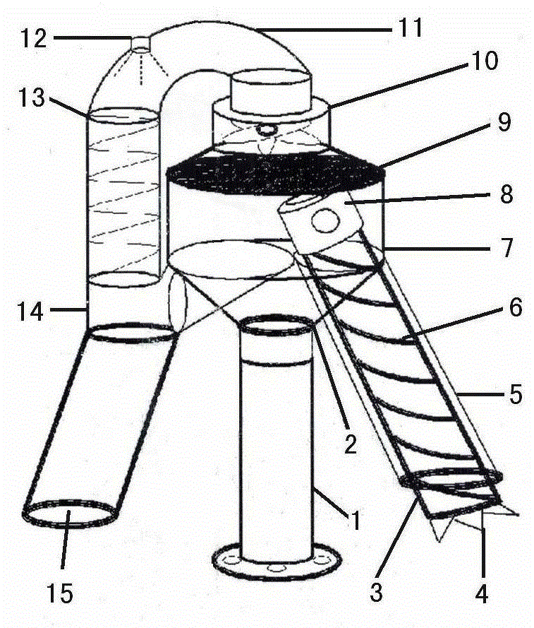
[0015] Implementation : As shown in the accompanying drawings, the spin-suction high-efficiency, energy-saving and environment-friendly loading and unloading machine of the present invention includes three parts: a support body, a spin unloading body, and a suction-discharging body.
[0016] The support body includes a straight strut 1 and a cross strut 2. The straight strut 1 is arranged on the lower end of the cross strut 2 and the upper end is connected with the lower side of one end of the cross strut 2, and its function is to support the cross strut. The cross strut 2 is arranged on the upper end of the straight strut 1 and the lower side of one end and is connected with the upper end of the straight strut 1, and its function is to support the unscrewing body and the suction and discharge body.
[0017] The spin unloading body includes a spin unloading pipe 3, a spin unloading scraper 6, a spinner 8, a tee pipe 14, and a discharge pipe 15, and the spin unloading pipe 3 i...
PUM
Abstract
The invention relates to a rotary suction high-efficiency, energy-saving and environment-friendly loading and unloading machine, which is composed of a rotary unloading pipe, a rotary unloading scraper, a rotary drive, a discharge pipe, a suction and discharge pipe, a rotary suction cover, a dust filter net, a vacuum cleaner, a dust reduction pipe, and a sprayer , dust retention tube and other organic comprehensive components. The spin unloading pipe is set on the inside of the suction and discharge pipe, the spin unloading scraper is set on the outside of the spin unloading pipe and is shaped like a spiral spatula, the rotary drive is set on the inside of the spin suction cover, the upper end of the discharge pipe is connected with the inside of the tee pipe, and the suction and discharge pipe is set On the outside of the spin unloading pipe and the spin unloading scraper, the inner side of the upper end of the spin suction cover is connected with the side of the dust filter, and the dust filter is set on the inner side of the upper end of the spin suction cover. They are respectively connected with the vacuum cleaner and the dust retention pipe, the sprayer is arranged inside the dust reduction pipe, the upper end of the dust retention pipe is connected with the lower end of the dust reduction pipe, and a spiral-shaped retardation convex groove is arranged therein. The invention has superior design performance, multi-functionality and wide practicality, safety, quickness and blockage prevention, dust prevention, noise prevention and pollution reduction, high efficiency, energy saving and environmental protection, reliability and durability, lower production cost and obvious comprehensive benefits.
Description
technical field [0001] The invention relates to a loading and unloading machine, in particular to a rotary suction high-efficiency, energy-saving and environment-friendly loading and unloading machine. Background technique [0002] With the rapid development and needs of national modernization construction and industrial and agricultural production, the loading and unloading volume and labor intensity of various bulk ore, coal, cement, fertilizer, grain, etc. are increasing, and the existing factories, mines, warehouses, stations, ports The technology of loading and unloading equipment lags behind, the speed is slow, the energy consumption is high, the efficiency is low, and the pollution such as noise and dust is serious. For this reason, it is particularly important to invent a loading and unloading machine with advanced technology, safety, high efficiency and energy saving and environmental protection. For this reason, the present inventor has invented a kind of spin-suc...
Claims
Application Information
Patent Timeline
Application Date:The date an application was filed.
Publication Date:The date a patent or application was officially published.
First Publication Date:The earliest publication date of a patent with the same application number.
Issue Date:Publication date of the patent grant document.
PCT Entry Date:The Entry date of PCT National Phase.
Estimated Expiry Date:The statutory expiry date of a patent right according to the Patent Law, and it is the longest term of protection that the patent right can achieve without the termination of the patent right due to other reasons(Term extension factor has been taken into account ).
Invalid Date:Actual expiry date is based on effective date or publication date of legal transaction data of invalid patent.

