Special gear pump

A gear pump, a special technology, used in pumps, rotary piston pumps, rotary piston machines, etc., can solve the problems of force and asymmetry of gear pumps that have never been seen before, and achieve great market application potential, symmetrical and uniform wear, simple structure

Inactive Publication Date: 2013-01-16
张意立
View PDF12 Cites 3 Cited by
  • Summary
  • Abstract
  • Description
  • Claims
  • Application Information

AI Technical Summary

Problems solved by technology

my country patent authorization announcement number: CN1059019C swing vane pump; my country patent authorization announcement number: CN100374725C rotary vane pump; The internal gear pump of plastic casing; my country's patent authorization announcement number: CN101120175B and my country's patent authorization announcement number: CN101403382B a kind of gear pump for micro-miniature turbojet engine, etc., all do not see that there is a practical method to solve the stress of the gear pump. Symmetry and face wear clearance control issues

Method used


Image

  • Special gear pump
  • Special gear pump
  • Special gear pump

Examples


Embodiment Construction

[0020] In conjunction with the accompanying drawings and embodiments, the structure and working principle of the present invention are further described in detail:

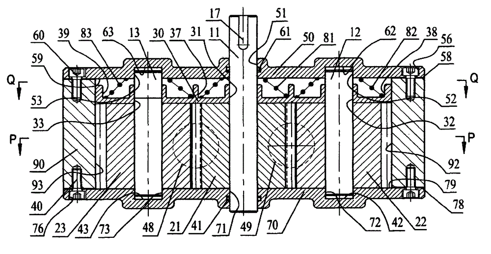
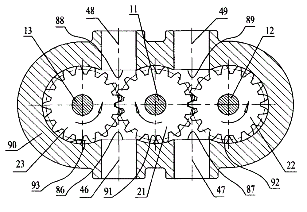
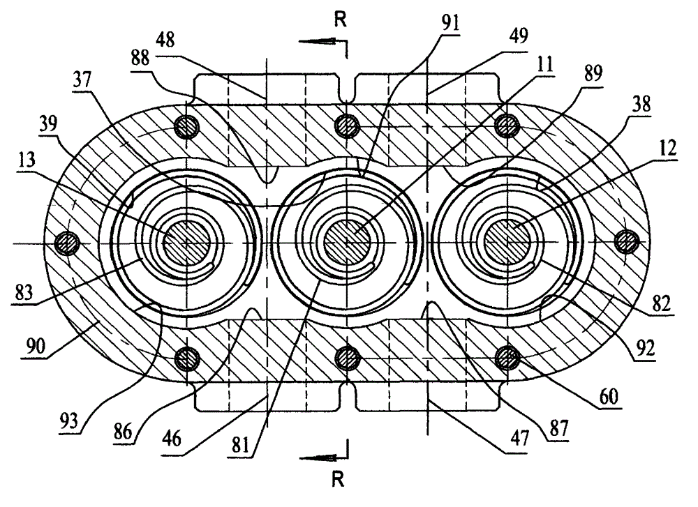
[0021] A special gear pump, including driving shaft 11, right driven shaft 12, left driven shaft 13, main gear 21, right driven gear 22, left driven gear 23, front outer end cover 50, rear outer end cover 70, middle Conical spring 81, right conical spring 82, left conical spring 83, pump body 90, as an improvement: the central two-section arc 91 on the inner cavity of the pump body 90 is slidingly fitted with the outer circle of the main gear 21; The right large half arc 92 on the cavity of the pump body 90 is slidably matched with the outer circle of the right slave gear 22; the left large semicircle 93 on the cavity of the pump body 90 is slidably matched with the left outer circle of the left slave gear 23; The drive shaft 11 at the center of the master gear 21 is parallel to the right driven shaft 12 at the ce...


PUM


Abstract

A special gear pump comprises a drive shaft, a right driven shaft, a left driven shaft, a main gear, a right driven gear, a left driven gear, a front outer end cover, a rear outer end cover, an intermediate conical spring, a right conical spring, a left conical spring and a pump body, wherein the improvement is that two central sections of arcs of an inner cavity of the pump body are in slide fit with an excircle of the main gear, a right large semi-arc of the inner cavity of the pump body is in slide fit with the excircle of the right driven gear, and a left large semi-arc of the inner cavity of the pump body is in slide fit with the excircle of the left driven gear; the drive shaft in the center of the main gear is parallel to the right driven shaft in the center of the right driven gear, and is also parallel to the left driven shaft in the center of the left driven gear; an inner plane of a rear cover of the rear outer end cover is closely fixed on the rear end face of the pump body; the inner plane of the front cover of the front outer end cover is closely fixed on the front end face of the pump body; and the right plane of a compensating disc on the end face is attached to the gear, the right driven gear and the left driven gear at the same time, and the intermediate conical spring, the right conical spring and the left conical spring are respectively arranged between the back side of the compensating disc on the end face and an inner plane of a front outer end.

Description

technical field [0001] The invention belongs to the field of mechanical engineering, and the international patent classification is F04D non-variable pump, which relates to an energy conversion rotary positive displacement pump which converts mechanical energy into liquid pressure energy, especially a special gear pump. Background technique [0002] The known gear pumps are all working in pairs. Due to the large pressure difference between the inlet and outlet, it is bound to cause unilateral force on the gear, especially the unilateral force on the driving gear, which directly causes unilateral wear and leakage at the shaft of the driving gear. As a result, the life of the gear pump is short and the pressure rise is limited. Another problem that has been plagued by gear pumps that cannot be effectively solved is that after long-term high-speed operation, the inevitable wear of the end face cannot be effectively compensated. my country patent authorization announcement numb...

Claims


Application Information

Patent Timeline
Patent Type & Authority Applications(China)
IPC IPC(8): F04C2/18
Inventor 张意立
Owner 张意立
Why Eureka
Try Eureka