
Circuit for LED constant current power supply
A constant current power supply and circuit technology, which is applied in the direction of electric lamp circuit layout, electric light source, light source, etc., can solve the problems of many peripheral devices, high cost, complicated circuit, etc. Effect
- Summary
- Abstract
- Description
- Claims
- Application Information
AI Technical Summary
Problems solved by technology
Method used
Image

Examples
Embodiment Construction
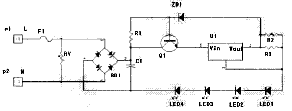
[0008] LED constant current power supply circuit of the present invention consists of figure 1 As shown, the AC voltage is input to the rectifier bridge composed of four diodes BD1 through the fuse F1 and the parallel varistor RV for rectification, and is filtered by the filter composed of the electrolytic capacitor C1. The output end of the electrolytic capacitor C1 is respectively connected to the collector of the transistor Q1 and the base resistor R1 of the triode Q1, the other end of the output of the electrolytic capacitor C1 is grounded, the emitter of the triode Q1 is connected to the input terminal Vin of the constant current IC chip U1, and the base of the triode Q1 is connected to the constant current through the voltage regulator ZD1. The output terminal Vout of the current IC chip U1 is connected, and the output terminal Vout of the constant current IC chip U1 is respectively connected to terminal 1 of the constant current IC chip U1 and the anode of LED1, LED2, LE...
PUM
 Abstract
Description
Claims
Application Information