Magnetic driving pump

A magnetic drive pump and pump cover technology, applied in the field of drive pumps, can solve the problems of easy deformation, easy wear and tear, rupture and leakage of the isolation sleeve, and achieve the effect of superior hydraulic comprehensive performance and clean and clean flow channels

Active Publication Date: 2013-03-06
上海佰诺泵阀有限公司
View PDF13 Cites 14 Cited by
  • Summary
  • Abstract
  • Description
  • Claims
  • Application Information

AI Technical Summary

Problems solved by technology

[0002] The two ends of the pump shaft of the traditional magnetic pump are generally fixed on the pump body and the spacer sleeve, and because of the magnetic transmission torque, the spacer sleeve is generally designed to be thin-walled as much as possible, which leads to the isolation sleeve when the pump is running for a long time. It is easy to deform or even scrape with the external magnetic steel to cause rupture and leakage; both ends of the pump shaft are fastened with threads; the circulation lubrication design of the sliding bearing pair is simple, and there is even air inside the isolation sleeve after the pump

Method used


Image

  • Magnetic driving pump
  • Magnetic driving pump
  • Magnetic driving pump

Examples


Embodiment Construction

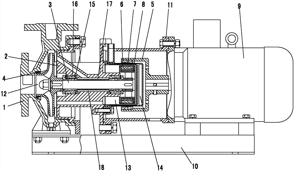
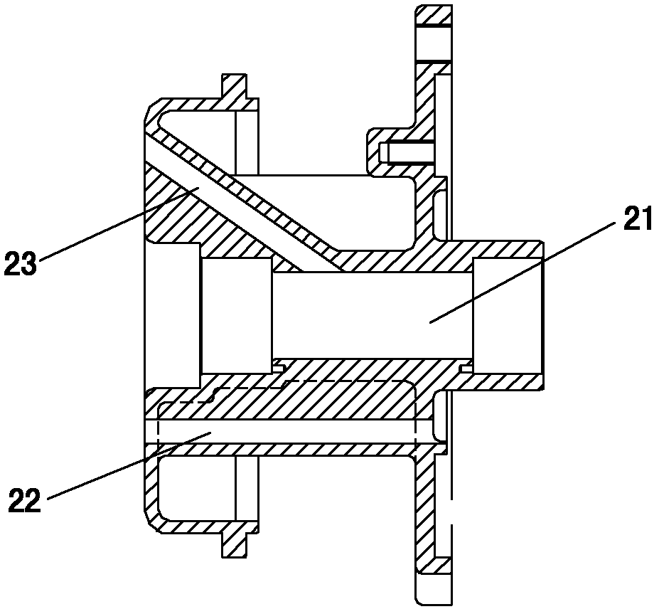
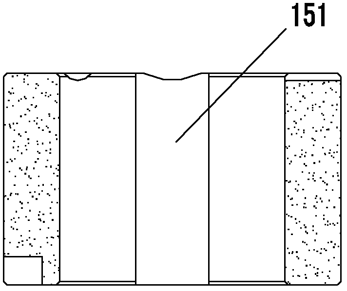
[0018] see figure 1 , with reference to Figure 2 to Figure 6 , the magnetic drive pump of the present invention comprises a pump body 1, a pump cover 2, a pump shaft 3, an impeller 4, an outer magnetic rotor 5, an inner magnetic rotor 6, a primary isolation sleeve 7, a secondary isolation sleeve 8 and a motor 9, the pump The body 1 and the motor 9 are installed on the base 10 . A connecting frame 11 is connected between the motor 9 and the pump cover 2 . A pump cavity 12 is formed between the pump cover 2 and the pump body 1, and an inner cavity 13 is formed between the pump cover 2, the inner magnetic rotor 6 and the primary isolation sleeve 7; the isolation sleeve is arranged between the outer magnetic rotor 5 and the inner magnetic rotor 6 , wherein the first-stage isolation sleeve 7 is arranged on the side close to the inner magnetic rotor 6, the second-level isolation sleeve 8 is arranged on the side close to the outer magnetic rotor 5, and an interval is provided betw...


PUM


Abstract

A magnetic driving pump comprises a pump body, a pump cover, a pump shaft, an impeller, an outer magnetic rotor, an inner magnetic rotor, an isolation sleeve and a motor. The isolation sleeve comprises a primary isolation sleeve and a second isolation sleeve, the primary isolation sleeve is arranged on one side close to the inner magnetic rotor, the secondary isolation sleeve is arranged on one side close to the outer magnetic rotor, and an interval is reserved between the primary isolation sleeve and the secondary isolation sleeve to form an isolation sleeve cavity. One side of the pump cover is provided with a through hole communicating a pump cavity with an inner cavity, and the other side of the pump cover is provided with a diagonal circulating hole. The front end of the circulating hole is communicated with the pump cavity at the front end of the pump cover, and the rear end of the circulating hole is communicated with a shaft hole. When a medium delivered by the pump is to be heated or cooled, an external heater/cooler is directly transmitted to the pump cavity, a sliding bearing pair and the inner cavity of the isolation sleeve to heat or cool the medium owing to the pump cover and the double-layer isolation sleeve. By the aid of the reasonable structural design, sufficient pressure and flow of all internal circulating and lubricating systems can guarantee stable running of the pump.

Description

technical field [0001] The invention relates to a driving pump, in particular to a magnetic driving pump. Background technique [0002] The two ends of the pump shaft of the traditional magnetic pump are generally fixed on the pump body and the spacer sleeve, and because of the magnetic transmission torque, the spacer sleeve is generally designed to be thin-walled as much as possible, which leads to the isolation sleeve when the pump is running for a long time. It is easy to deform or even scrape with the external magnetic steel to cause rupture and leakage; both ends of the pump shaft are fastened with threads; the circulation lubrication design of the sliding bearing pair is simple, and there is even air inside the isolation sleeve after the pump is filled with liquid before operation, resulting in this The phenomenon of dry running of the pump, when maintaining the pump, there are even some corrosive media in some isolation sleeves; the bearing sleeves are generally made ...

Claims


Application Information

Patent Timeline
IPC IPC(8): F04D13/02
Inventor 周大财
Owner 上海佰诺泵阀有限公司
Why Eureka
Try Eureka