
Magnetic sensor with low electric offset

A magnetic sensor and offset value technology, applied in the field of magnetic sensors, can solve the problems of impracticality, large electrical offset of AMR sensors, and reduced sensitivity

Inactive Publication Date: 2013-03-06
NXP BV
View PDF5 Cites 24 Cited by
  • Summary
  • Abstract
  • Description
  • Claims
  • Application Information

AI Technical Summary

Problems solved by technology

AMR sensors typically have relatively high sensitivity compared to other magnetic sensors; however, AMR sensors typically experience large electrical offsets
Conventional methods for filtering the offsets are often impractical due to the size or complexity of the components used to filter the offsets or even loss of information in some applications
Additionally, modulated AMR sensors used to reduce or eliminate offset can introduce noise and desensitize the input

Method used


Image

  • Magnetic sensor with low electric offset
  • Magnetic sensor with low electric offset
  • Magnetic sensor with low electric offset

Examples


Embodiment Construction

[0015] It will be readily understood that the elements of the embodiments as generally described herein and illustrated in the drawings may be configured and designed in a variety of different configurations. Accordingly, the ensuing more detailed description of various embodiments as represented in the drawings is not intended to limit the scope of the present disclosure, but is merely representative of various embodiments. While the various aspects of the embodiments are presented in drawings, the drawings are not necessarily drawn to scale unless specifically indicated.

[0016] The present invention may be embodied in other specific forms without departing from the spirit or essential characteristics of the inventions. The described embodiments are to be considered in all respects only as illustrative and not restrictive. Accordingly, the scope of the invention is indicated by the appended claims rather than by this detailed description. All changes that come within the ...


PUM


Abstract

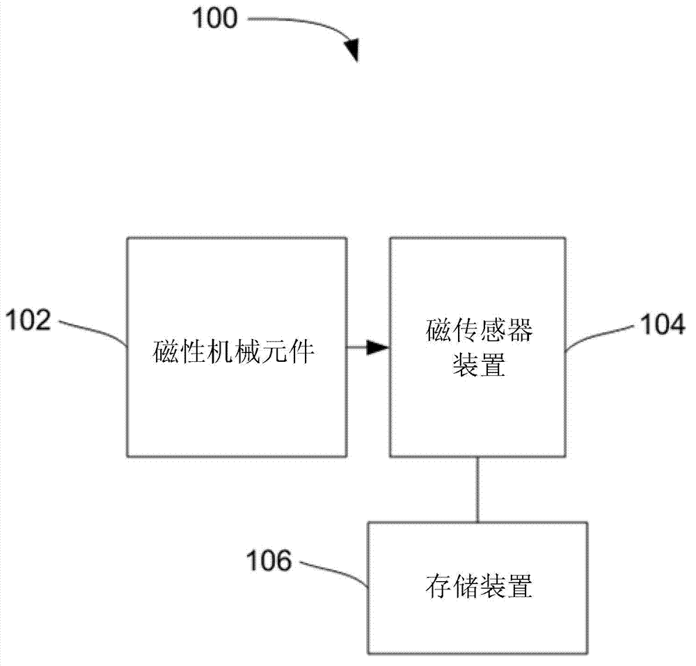
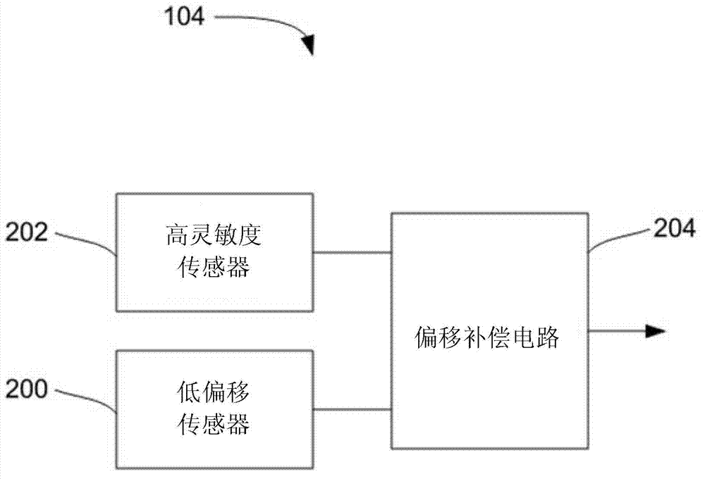
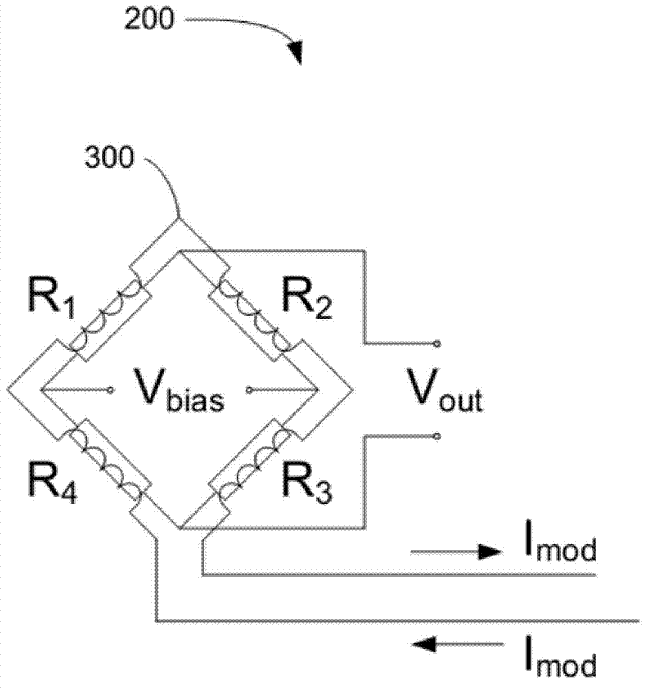
The invention discloses a magnetic sensor device with low electric offset and high sensitivity, a method thereof, and a magnetic sensing system. The magnetic sensing system includes: a magnetic component proximate a movable mechanical component; and a magnetic sensor configured to determine a movement of the mechanical component based on a magnetic field produced by the magnetic component. The magnetic sensor includes: a low-offset magnetic sensing element; a high-sensitivity magnetic sensing element; and an offset compensation circuit configured to: determine a zero-crossing of a sensing field from an output of the low-offset magnetic sensing element; sample an offset value of the high-sensitivity magnetic sensing element at the zero-crossing; and subtract the offset value from an output of the high-sensitivity magnetic sensing element.

Description

technical field [0001] The invention relates to a magnetic sensor. Background technique [0002] Magnetic sensors used in conjunction with permanent magnets or other magnetic elements can be used to detect the position and velocity of mechanical elements. By connecting the magnetic element to the mechanical element or to a magnetic sensor arrangement proximate to the mechanical element, rotation or other movement of the mechanical element causes a change in the magnetic field produced by the magnetic element, which change can then be detected by the magnetic sensor. Analyzing the output of the sensor and knowing the mechanical structure of the mechanical element allows the determination of the frequency of the time-varying magnetic field at the location of the magnetic sensor and the velocity of the mechanical element. [0003] Anisotropic magnetoresistive (AMR) sensors are commonly used as magnetic field sensors for such applications. AMR sensors typically have relatively...

Claims


Application Information

Patent Timeline
IPC IPC(8): G01D5/12
CPCG01R33/0029G01R33/09G01R33/0017
Inventor 法比奥·塞巴斯蒂亚诺罗伯特·亨里克斯·玛格丽塔·范费尔德温
Owner NXP BV
Learn More