Manufacturing method of organic el display panel and manufacturing device of organic el display panel

A technology of a display panel and a manufacturing method, which is applied in the directions of identification devices, lighting devices, semiconductor/solid-state device manufacturing, etc., can solve problems such as complex control of inkjet devices

Active Publication Date: 2016-01-13
JOLED INC
View PDF8 Cites 0 Cited by
  • Summary
  • Abstract
  • Description
  • Claims
  • Application Information

AI Technical Summary

Problems solved by technology

However, there is a problem that if all the nozzles of the inkjet head are required to generate the driving voltage of the desired waveform, the inkjet device has to perform very complicated control.

Method used


Image

  • Manufacturing method of organic el display panel and manufacturing device of organic el display panel
  • Manufacturing method of organic el display panel and manufacturing device of organic el display panel
  • Manufacturing method of organic el display panel and manufacturing device of organic el display panel

Examples


Embodiment approach 1

[0049] [the whole frame]

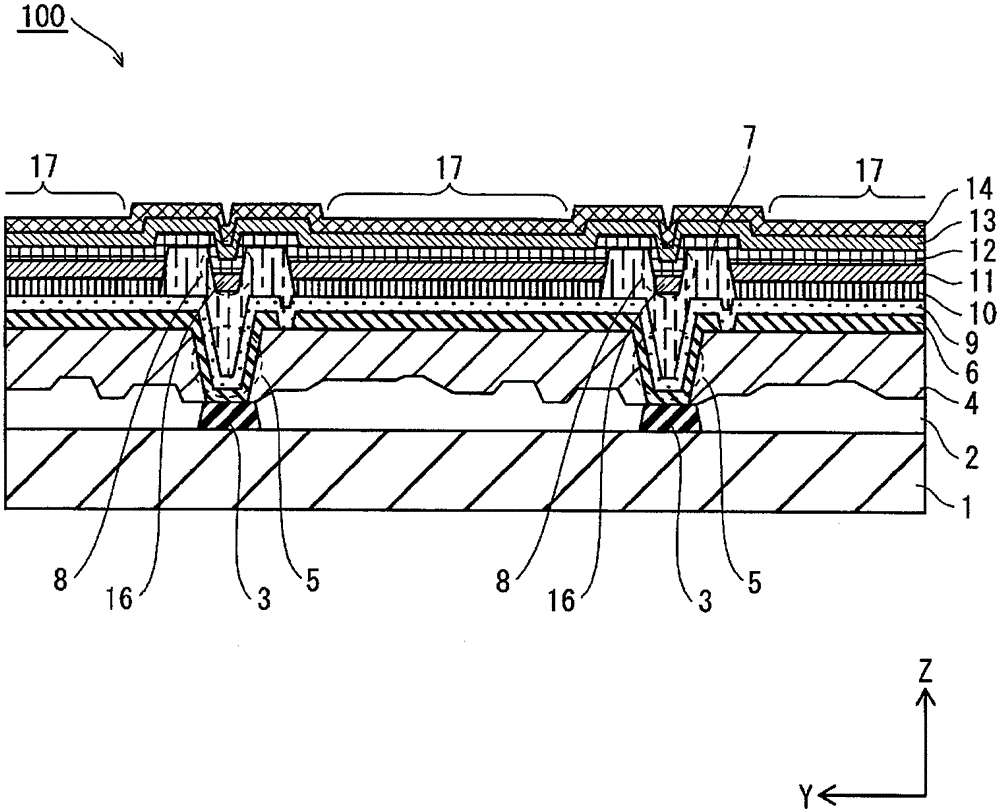
[0050] figure 1 It is a partial cross-sectional view showing the structure of the organic EL display panel 100 according to the first embodiment. The organic EL display panel 100 is a so-called top emission type in which the upper side in the figure is defined as a display surface.

[0051] like figure 1 As shown, a TFT layer 2 , a power supply electrode 3 , a planarization film 4 , a pixel electrode 6 , and a hole injection layer 9 are sequentially stacked on a substrate (EL substrate) 1 . On the hole injection layer 9 , the partition wall layer 7 is provided with a plurality of openings 17 serving as formation regions of the organic light emitting layer 11 . Inside the opening 17 , the hole transport layer 10 , the organic light-emitting layer 11 , the electron transport layer 12 , the electron injection layer 13 , and the counter electrode 14 are laminated in this order.

[0052]

[0053] The substrate 1 is a rear substrate of the organic EL...

Embodiment approach 2

[0219] Figure 18 It is a diagram showing the control flow of the ejection frequency control unit in the step of selecting nozzles for ejecting liquid droplets according to the second embodiment.

[0220] Figure 18 Steps S901, S902, S904-S906, S908-S911 in the Figure 9 S201, S202, S204~S206, S208~S211 in the corresponding. and Figure 9 The difference is that S912A and S913A are provided.

[0221] In this embodiment, when the judgment is N A When ×T is less than the necessary number of discharges N (droplets equal to or greater than the target value cannot be discharged only by the A-class nozzle) (No in step S902), it is determined whether the maximum number of discharges T can be further increased (step S912A). The maximum number of discharges T can be increased by changing the waveform of the drive voltage applied to the piezoelectric element to increase the discharge frequency, or by reducing the scanning speed of the inkjet head.

[0222] When it is determined tha...


PUM


Abstract

Provided is a method of manufacturing an organic EL display panel that can uniformize the total volume of liquid droplets discharged to openings by simple control. Including: the first step, preparing the EL substrate formed with the opening 17 and the head 301 configured with a plurality of nozzles 3030; the second step, detecting the volume of droplets discharged from each nozzle 3030 per unit number of times per nozzle; the second step Step 3, divide the nozzles 3030 into nozzle groups a1, a2, a3, a4 corresponding to the openings 17 one-to-one, and each nozzle group a1, a2, a3, a4, based on the The detected inhomogeneity of the droplet volume determines the number of discharges of the droplets carried out by the nozzle 3030 for each nozzle, so that the total amount of droplet volume discharged to the opening 17 becomes the reference range; and the fourth step is to make the head 301 While scanning in the row direction, liquid droplets are discharged from the nozzles 3030 belonging to the corresponding nozzle group to the openings 17 at the number of discharges determined for each nozzle in the third step.

Description

technical field [0001] The present invention relates to a method for manufacturing an organic EL display panel including an organic EL element, and an apparatus for manufacturing an organic EL display panel. Background technique [0002] In recent years, an organic EL display panel in which an organic EL element is arranged on a substrate has become widespread as a display device. The organic EL display panel has features such as high visibility because it uses an organic EL element that emits light by itself, and excellent impact resistance because it is a completely solid element. [0003] The organic EL element is a current-driven light-emitting element, and is constituted by laminating an organic light-emitting layer or the like that performs an electroluminescent phenomenon by carrier recombination (recombination) between an electrode pair of an anode and a cathode. In addition, in the organic EL display panel, the organic EL elements corresponding to the respective co...

Claims


Application Information

Patent Timeline
Patent Type & Authority Patents(China)
IPC IPC(8): H05B33/10G09F9/30H01L27/32H01L51/50H05B33/12
CPCH10K71/135H10K59/1201H05B33/10H10K59/12
Inventor 竹内孝之
Owner JOLED INC
Why Eureka
Try Eureka