Hydraulic centering cylinder with mechanical lockup function

A mechanical lock and function technology, applied in the direction of hydraulic steering gear, fluid pressure actuating device, etc., can solve the problems of deteriorating the driving stability of the vehicle and only elastic locking.

Inactive Publication Date: 2013-04-17
BEIJING INSTITUTE OF TECHNOLOGYGY
View PDF8 Cites 12 Cited by
  • Summary
  • Abstract
  • Description
  • Claims
  • Application Information

AI Technical Summary

Problems solved by technology

[0004] The purpose of the present invention is to solve the problem that the existing technology can only be locked elastically, and the driving stability of the vehicle...

Method used


Image

  • Hydraulic centering cylinder with mechanical lockup function
  • Hydraulic centering cylinder with mechanical lockup function
  • Hydraulic centering cylinder with mechanical lockup function

Examples


Embodiment 1

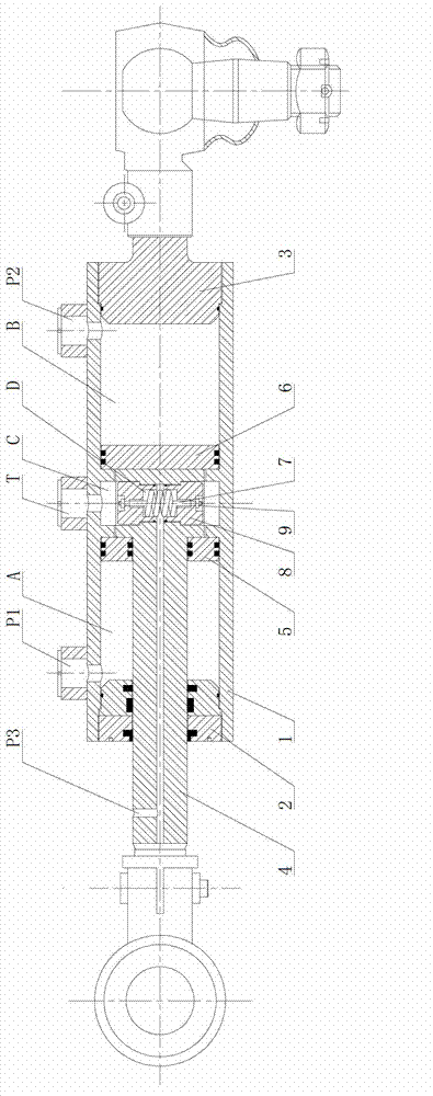
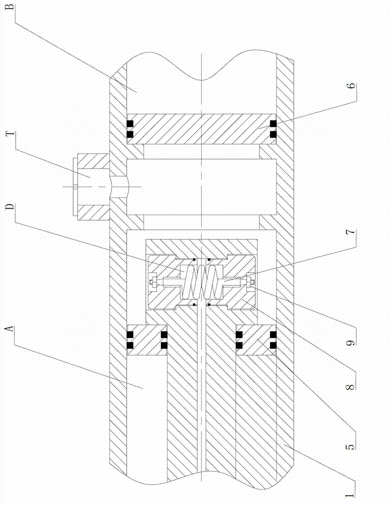
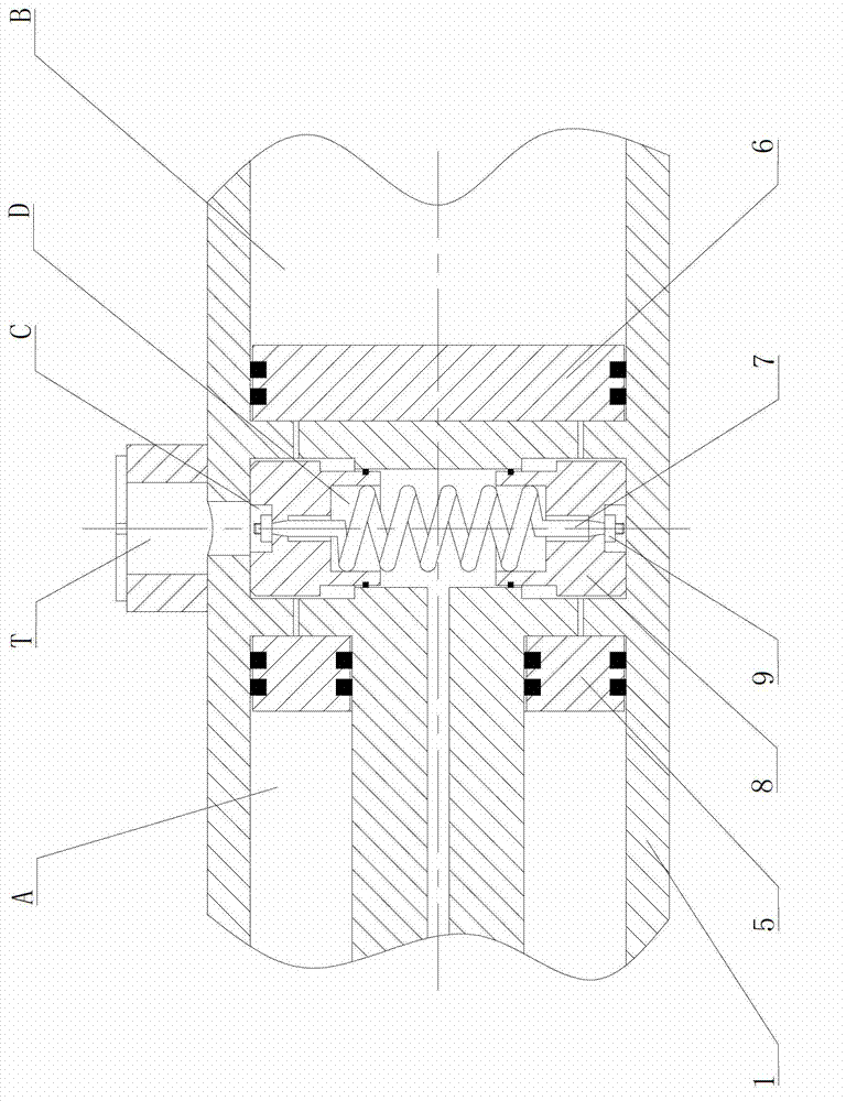
[0018] A hydraulic centering cylinder with mechanical locking function, including: cylinder block, piston rod, left cylinder end cover, right oil cylinder end cover, left floating piston, right floating piston; also includes: spring, locking piston and nut ;Such as figure 1 shown.

[0019] The hydraulic centering function is composed of cylinder block 1, left cylinder end cover 2 and right cylinder end cover 3, piston rod 4, left floating piston 5, right floating piston 6, etc. The two ends of the left oil cylinder end cap 2 and the right oil cylinder end cap 3 are internally threaded and sealed with the oil cylinder body 1 . The piston rod 4 is located in the oil cylinder body 1, and an annular boss is arranged at one end inside it. The left floating piston 5 and the right floating piston 6 are installed on both sides of the annular boss respectively. The middle of the oil cylinder block 1 is designed with left and right inner ring platforms which are matched with the annu...


PUM


Abstract

The invention relates to a hydraulic centering cylinder with a mechanical lockup function and belongs to the field of automobile steering systems. The hydraulic centering cylinder comprises an oil cylinder body, a piston rod, a left oil cylinder end cover, a right oil cylinder end cover, a left floating piston, a right floating piston, a spring, lockup pistons and nuts. The installation method of the hydraulic centering cylinder includes that the spring is strung in axis through holes of the two lockup pistons which are vertically and symmetrically arranged, then the integrated spring and lockup pistons are placed in a groove of an annular boss of the piston rod, and finally, two ends of the spring are tensioned by the nuts to finish assembling. By means of extension and retraction of the two lockup pistons, integration and separation of the piston rod and a cylinder body through relative movement are achieved, and accordingly, mechanical lockup and unlocking of the piston rod during movement are achieved. By means of mechanical lockup, slight moving of the piston rod under large impacting is prevented, and simultaneously, safety guarantee is provided for hydraulic centering. When unlocking is required, only working oil pressure is required to be removed, and the lockup pistons are automatically retracted to the groove of the annular boss of the piston rod to finish unlocking under the action of spring forces.

Description

technical field [0001] The invention belongs to an auxiliary device of an automobile rear wheel steering system, specifically a hydraulic centering cylinder with a mechanical locking function, and belongs to the field of automobile steering systems. Background technique [0002] With the widespread use of multi-axle technology on heavy-duty vehicles and military vehicles, problems such as severe tire wear, large turning radius, and poor handling stability have emerged accordingly. Rear-wheel steering technology can be said to be the best solution to these problems. Among them, the electro-hydraulic rear wheel steering technology has the most advantages. The electronic control unit can accurately realize the extension and retraction distance of the piston rod of the hydraulic steering cylinder by controlling the flow and direction of the hydraulic valve. The displacement of the rod realizes the precise control of the rear wheel's turning angle. The use of electronically con...

Claims


Application Information

Patent Timeline
IPC IPC(8): B62D3/14F15B15/08F15B15/26
Inventor 陈思忠郑凯锋杨林吴志成
Owner BEIJING INSTITUTE OF TECHNOLOGYGY
Why Eureka
Try Eureka