
Front-rear view integrated mirror

A one-piece, mirror mount technology, applied in optical observation devices, transportation and packaging, vehicle parts, etc., can solve the problem of reducing the visible range of rearview mirrors

Inactive Publication Date: 2013-04-24
KUNDA COMP TECHKUSN
View PDF1 Cites 0 Cited by
  • Summary
  • Abstract
  • Description
  • Claims
  • Application Information

AI Technical Summary

Problems solved by technology

However, the front-view device in the Chinese mainland patent application No. 201020537076.5 divides the viewing area of ​​the rear-view mirror, reducing the viewing range of the rear-view mirror

Method used


Image

  • Front-rear view integrated mirror
  • Front-rear view integrated mirror
  • Front-rear view integrated mirror

Examples


Embodiment Construction

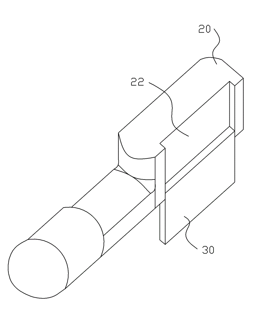
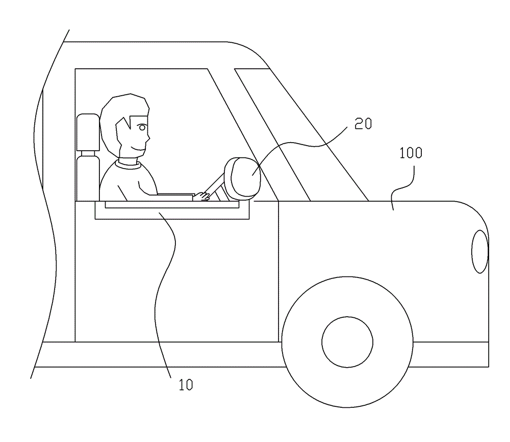
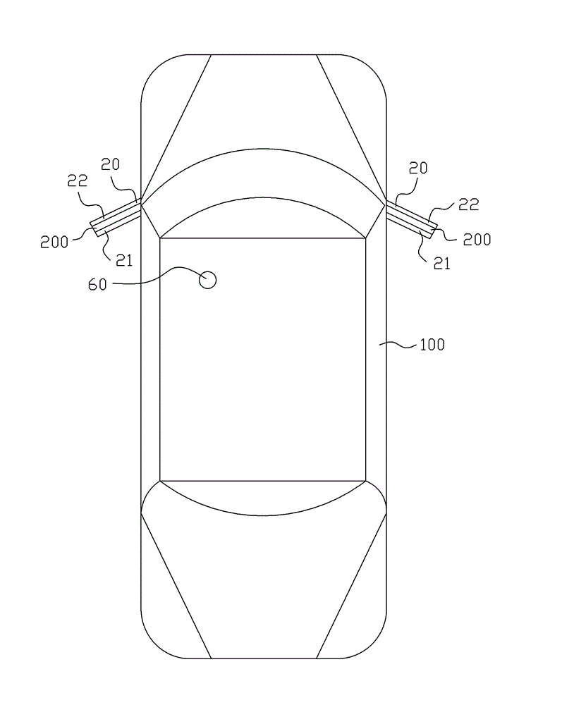
[0015] see figure 1 , figure 2 and Figure 4 As shown, the present invention provides a front and rear viewing integrated mirror, which includes a linear track 10 and a mirror base 20. The linear track 10 is arranged on both sides of the vehicle body 100, and the two ends of the linear track 10 correspond to the first position and the second position respectively. Two positions; the mirror base 20 is rotatably arranged on both sides of the vehicle body 100 and is provided with a first mirror surface 21 and a second mirror surface 22, and the first mirror surface 21 and the second mirror surface 22 are set against the back; the mirror base 20 is arranged along the The mirror base 20 slides between the first position and the second position. In this embodiment, the second mirror 22 is provided with a windshield 30 outside. When the windshield 30 is kept open, the second mirror 22 is exposed; and when the windshield 30 is kept closed, the second The second mirror surface 22 i...


PUM


Abstract

The invention provides a front-rear view integrated mirror which comprises a linear rail and a mirror base. The linear rail is arranged at both sides of a car body. Two ends of the linear rail are respectively corresponding to a first position and a second position. The mirror base is arranged on both sides of a car body in a rotating mode and provided with a first mirror surface and a second mirror surface, wherein the first mirror surface and the second mirror surface are arranged in an opposite mode. The mirror base slides in the linear rail and between the first position and the second position. When the mirror base moves to the first position, people can watch rear road condition through the first mirror surface. When the mirror base moves to the second position, people can watch front blind area through the second mirror surface. According to the front-rear view mirror, the position of the mirror base is needed adjusting and choice of the first mirror surface or the second mirror surface is made according to need, while the size of a rear view mirror is not changed, so field of view is not affected.

Description

【Technical field】 [0001] The invention relates to a front and rear viewing integrated mirror, in particular to a front and rear viewing integrated mirror which does not affect the visual range. 【Background technique】 [0002] Existing motor vehicles are equipped with reflectors, and the driver can understand road traffic conditions by the reflectors, so that the motor vehicles are operated when driving. Current reflectors are generally rearview mirrors installed on the vehicle body, which can only understand the traffic conditions behind the motor vehicle. The driver's seat on the motor vehicle is offset on the side of the cab. If there is an obstacle in the front blind spot, it will block the driver's sight, so that the driver cannot see various situations on the left and right sides of the front. In addition, existing motor vehicles often need someone to direct and can be successfully completed due to only the rearview mirror when parking and crossing the path. [0003] ...

Claims


Application Information

Patent Timeline
Patent Type & Authority Applications(China)
IPC IPC(8): B60R1/06B60R1/10
Inventor 许世法
Owner KUNDA COMP TECHKUSN
Learn More