
LED screen

A technology of LED screen body and LED light bar, which is applied in the direction of instruments and identification devices, which can solve the problems of affecting the visual range, inconvenient, and bulky frames with box display screens, and achieve good heat dissipation effect, transparent products, The effect of simple structure

Inactive Publication Date: 2012-11-28
范红霞
View PDF0 Cites 0 Cited by
  • Summary
  • Abstract
  • Description
  • Claims
  • Application Information

AI Technical Summary

Problems solved by technology

[0003] In the existing LED display screen, on the opaque flat plate structure, one pixel is composed of LEDs, and each pixel is arranged in a matrix at a certain interval to form a unit board with patterns and text information. Since the light-emitting pixels of the display screen are all set at different The light-transmitting planar structure limits the application of the display screen in some occasions or cannot play a better effect
For example, installing a large-area conventional LED display outside or inside the glass curtain wall of a building will seriously affect the lighting inside the building and the visual range of people in the building, or affect the visual range viewed from the outside of the building.
In daily LED display applications, most of them are assembled by several small display screens with cabinets, but the frame with display screens with cabinets is too bulky, which is very inconvenient during installation and moving. It is not easy to replace the broken part of the display, which brings inconvenience to the user in the process of using the LED display

Method used


Image

  • LED screen
  • LED screen
  • LED screen

Examples


Embodiment 1

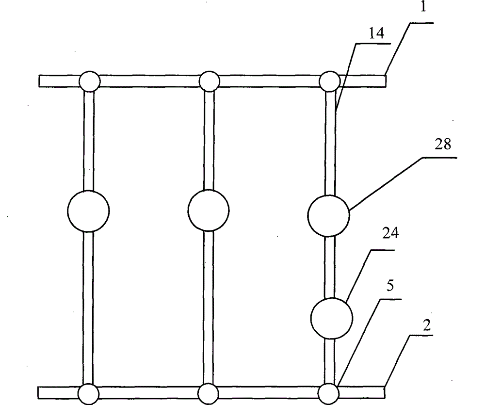
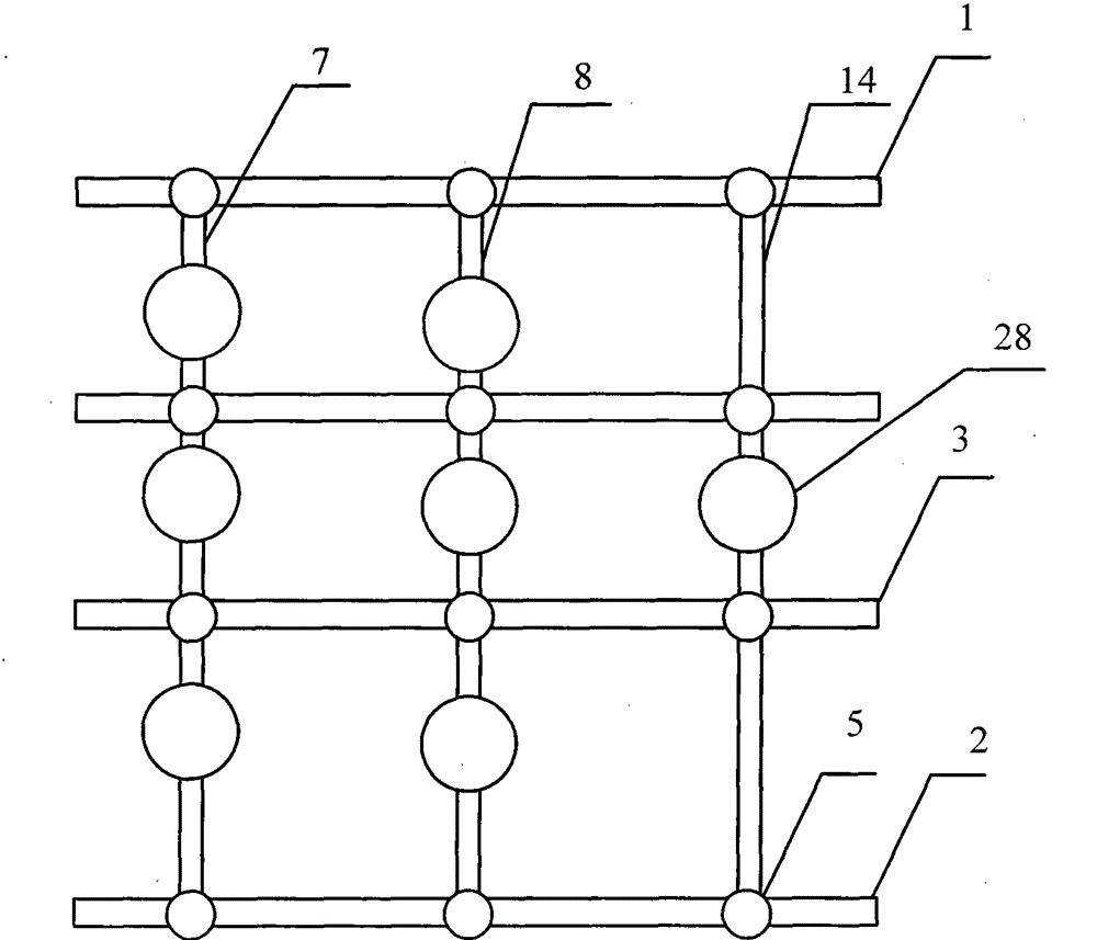
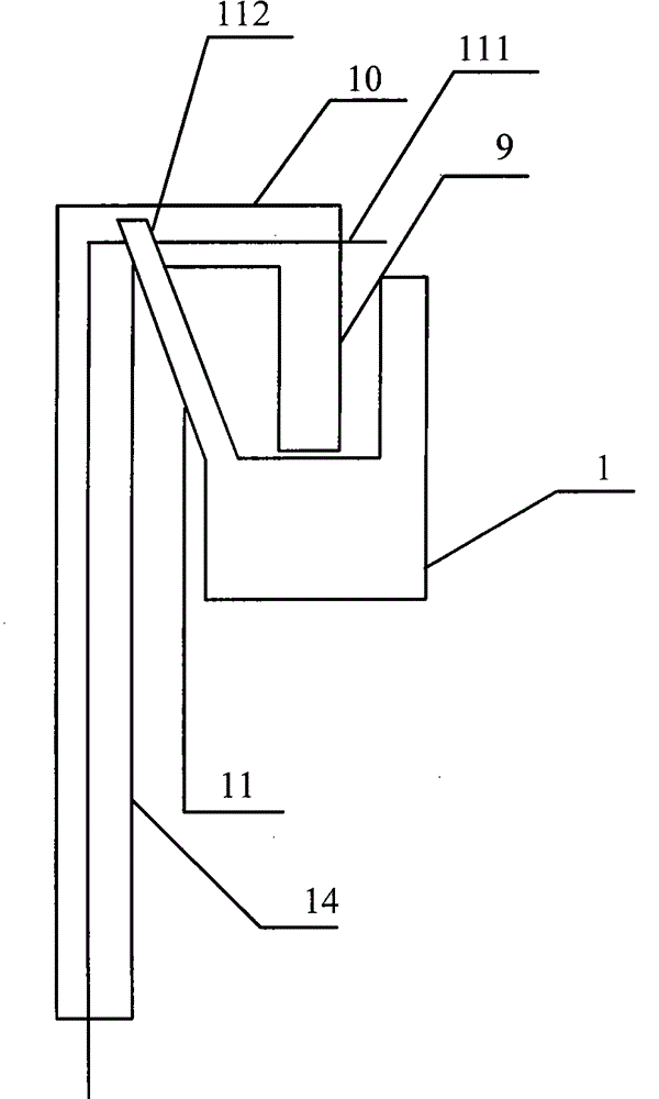
[0030] Such as figure 1 and image 3 As shown, the present invention provides an LED screen, which includes an upper beam 1 , a lower beam 2 and at least one LED light bar 14 .

[0031] The LED light bar 14 includes a set of connectors 9, at least one load-bearing portion 10, at least one lower fixing portion 5, at least two LED units, such as an LED unit 24 and an LED unit 28, at least one positive power supply line, at least one negative power supply line and At least one signal line, wherein any LED unit includes at least one LED light emitting diode and its control module.

[0032] The upper beam 1 is provided with at least one supporting part 11, and the LED light bar 14 is provided with at least one bearing part 10, and the bearing part 10 is fixed on the supporting part 11; an LED light bar 14 is arranged on a supporting part through a bearing part 10 11, and maintain the position of the LED light bar, that is, keep the LED light bar 14 on a certain position of the up...

Embodiment 2

[0047] Such as Figure 6 As shown, on the basis of Embodiment 1, in the LED light bar, each line is combined into a flat line 111; the flat line 111 includes the first power supply positive line 20, the first power supply negative line 21 and the first signal The line 13, these three lines form a strip-shaped cable 111, and the cable 111 is provided with at least two fixing positions for fixing each LED unit; each LED unit is fixed on the fixing position of the cable.

[0048] At the connection between the LED light bar and the crossbeam, the first power supply positive line 20, the first power supply negative line 21 and the first signal line 13 form a cable, and two T-shaped fixing positions 22 are set on the cable, and every two T The font fixing position 22 is a pair, which is used to fix an LED unit, and a plurality of LED units are connected in series to form an LED light bar through a cable; in order to better control the LED light-emitting diodes 25 on each LED unit, e...

Embodiment 3

[0055] In Embodiment 2, each line in the LED light bar can also be combined into a multi-strand line; the multi-strand line includes the first power supply positive line 20, the first power supply negative line 21 and the first signal line 13 , these three wires form a multi-strand wire, these three wires are flexible, and at least two fixing positions are arranged on the multi-strand wire for fixing each LED unit; each LED unit is fixed on the fixing part of the multi-strand wire bit.

[0056] The load-bearing part 10 and the supporting part 11 can also be arranged in other connection methods such as clip connection or screw connection according to actual needs. The LED light bar 14 is electrically connected and signal connected with a set of interfaces on the upper beam 1 through a set of joints 9; the first power supply positive line and the first power negative line and the first power supply negative line are arranged in the joint 9 on the LED light bar 14. For the signa...


PUM


Abstract

The invention discloses an LED screen body, which comprises an upper cross beam, a lower cross beam and at least one LED lamp strip, wherein the LED lamp strip comprises at least one group of joints, at least one bearing part, at least one lower fixing part, at least two LED units, at least one anode power line, at least one cathode power line and at least one signal line; each LED unit comprisesat least one LED light-emitting diode and a control module of the LED light-emitting diode; the upper cross beam is provided with at least one supporting part, and the lower cross beam is provided with at least one group of lower fixing ports; the LED screen body is provided with at least one group of interfaces which are arranged corresponding to the joints, and power lines and signal lines which are parallel to various groups of interfaces; and electrical connection and signal connection of various LED lamp strips are realized through a group of joints and a group of interfaces. The invention provides the LED screen body which is more flexible to assemble and more convenient to move and has a simpler structure and lower cost.

Description

technical field [0001] The invention relates to an illuminating device, in particular to an LED screen body. Background technique [0002] As an important means of information dissemination, LED display has become a symbol of urban information modernization. With the continuous progress of social economy and the continuous improvement of LED display technology, people's understanding of LED display screens will become deeper and deeper, and its application fields will become wider and wider. [0003] In the existing LED display screen, on the opaque flat plate structure, one pixel is composed of LEDs, and each pixel is arranged in a matrix at a certain interval to form a unit board with patterns and text information. Since the light-emitting pixels of the display screen are all set at different Due to the light-transmitting planar structure, the application of the display screen in some occasions is limited or cannot exert a better effect. For example, installing a large-a...

Claims


Application Information

Patent Timeline
Patent Type & Authority Patents(China)
IPC IPC(8): G09F9/33
Inventor 商松
Owner 范红霞
Learn More