Electrical limitation of a steering gear travel path

A steering device, stroke technology, applied in the direction of automatic steering control components, steering mechanisms, steering rods, etc., to achieve easy and repeatable effects

Inactive Publication Date: 2013-05-08
GM GLOBAL TECH OPERATIONS LLC
View PDF5 Cites 6 Cited by
  • Summary
  • Abstract
  • Description
  • Claims
  • Application Information

AI Technical Summary

Problems solved by technology

[0002] The free space of the wheel in the wheel housing limits the possible steering angles

Method used


Image

  • Electrical limitation of a steering gear travel path
  • Electrical limitation of a steering gear travel path
  • Electrical limitation of a steering gear travel path

Examples


Embodiment Construction

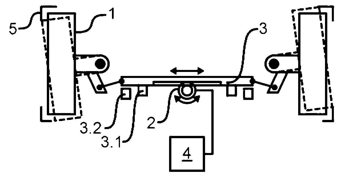
[0028] figure 1 A steering arrangement of a passenger car with two wheels 1 housed in wheel housings 5 ​​steered by means of a steering rack 3 is shown schematically according to an exemplary embodiment of the invention. To move the steering rack 3, the electric motor 2 of the steering drive meshes with said steering rack 3, said motor 2 supporting the steering movement of a steering rod (not shown) operatively connected to the steering wheel, or based on a detected The steering operation of the steering wheel makes the steering rack separate from the steering wheel move independently.

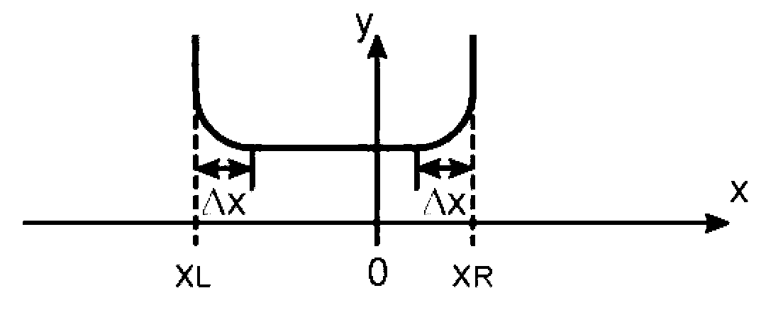
[0029] In addition to the electric motor 2 , the steering drive also includes, in particular, a controller 4 which is signal-connected to the electric motor 2 . The controller 4 activates the electric motor 2 and receives information from the electric motor 2 in particular about the real-time adjustment travel x (cf. image 3 ), such as the position of the steering rack 3 or the rotation angle...


PUM


Abstract

A method for an electrical limitation of the travel path of a steering gear (2, 4) in a wheeled vehicle, in particular a passenger car, which exhibits a steering drive, is provided. The method includes adjusting (S20) the steering gear in a first direction and acquiring (S20) a first maximum travel path (xL) in the first direction. The method includes prescribing (S30) a first limiting value (xL+deltax) based upon this acquired first maximum travel path (xL) and electrically limiting (S70) the travel path of the steering gear in the first direction based upon the first limiting value (xL+deltax). The first maximum travel path (xL) is acquired by the steering drive (2, 4).

Description

technical field [0001] The present invention relates to a method for electrically limiting the adjustment stroke (also known as execution stroke or working stroke) of a steering device of a wheeled vehicle, especially a car, and a steering device for performing the method. Background technique [0002] The free space of the wheel within the wheel housing limits the possible steering angles. In particular, the steering angle is limited in order to avoid contact of the steered wheels with the wheel housings. [0003] In order to set permissible steering angles for multiple structurally identical vehicles under different dynamic conditions, it is necessary to take into account dynamic changes, such as spring deflection runouts, on the one hand, and the components between the different vehicles on the other hand and assembly tolerances, such as different assembly distances from the wheel to the wheel housing. This dynamic and tolerance-based safety distance within the permissi...

Claims


Application Information

Patent Timeline
Patent Type & Authority Applications(China)
IPC IPC(8): B62D5/04B62D6/00B62D7/00
CPCB62D15/02B62D5/0469B62D3/12
Inventor T.德根斯坦
Owner GM GLOBAL TECH OPERATIONS LLC
Why Eureka
Try Eureka