Structural unit with axial adjustment limiting elements

a technology of limiting elements and structural units, applied in the direction of couplings, rod connections, manufacturing tools, etc., can solve the problems of failure of such a tie rod, damage to the threads, and even total removal of the shank from the adjustment sleeves

Inactive Publication Date: 2014-04-15
ZF FRIEDRICHSHAFEN AG
View PDF21 Cites 6 Cited by
  • Summary
  • Abstract
  • Description
  • Claims
  • Application Information

AI Technical Summary

Benefits of technology

[0006]The technical object of the invention is to provide a structural unit having two structural elements that are adjustable relative to each other, which makes it possible to limit the axial adjustment travel, and that is reliable and simple to produce.
[0008]With the solution according to the invention, an undesired loosening of the individual parts of the presented structural unit can be securely and reliably avoided. The available, limited axial adjustment travel of the structural components relative to each other is defined by this embodiment in a simple manner. Due to the fact that the shank penetrates the blocking element, the blocking element can be disposed within the structural unit. Consequently, the blocking element is protected from mechanical, thermal and chemical influences, thereby representing a reliable protection which is guaranteed for the entire service life of the structural unit. However, the solution according to the invention also has further advantages, such as the avoidance of an improper adjustment movement of the structural unit, or the simple construction of the structural unit. The product can be accepted directly into already existing series products without significant expenditure.
[0010]The blocking element should preferably be inserted into a groove introduced in the inner lateral surface of the adjustment sleeve. Thus, the adjustment sleeve together with the blocking element can be produced as a preassembled structural unit before the final assembly of the structural unit according to the invention. The overall assembly is thereby simplified.
[0011]A further development of this solution consists of inserting the blocking element without axial play into the groove in the inner lateral surface of the adjustment sleeve, but with clearance in the radial direction. The radial play within the groove for receiving the blocking element makes it possible to use the inherent elasticity of the blocking element which is significant for the assembly of the structural unit.

Problems solved by technology

Consequently, the smaller diameter thread represents a weak point which could lead to failure with such a tie rod.
Beyond this, a further disadvantage with such solutions turns out to be that the shank is inadvertently turned so far out of the adjustment sleeve that receives it that only a small section of thread is available for the transfer of force, or that the shank is even completely removed from the adjustment sleeve.
This risk is additionally increased by damaged threads.
Although the solution described in the document makes possible expedient limiting of the axial travel during adjustment of the structural unit, the manufacturing expenditure for producing the planar surface at the shank is a disadvantage.
In addition, this variant embodiment involves a significant assembly expenditure.
A further disadvantage is that the metal strip is located outside of the tie rod, and therefore, damage or deformation to the metal strip during the intended use of the tie rod in motor vehicles cannot be excluded so that its function could possibly be negated.
In addition, this sheet metal section is subject to increased environmental influences, and therefore there is a risk of it corroding or wearing prematurely.

Method used


Image

  • Structural unit with axial adjustment limiting elements
  • Structural unit with axial adjustment limiting elements
  • Structural unit with axial adjustment limiting elements

Examples


Embodiment Construction

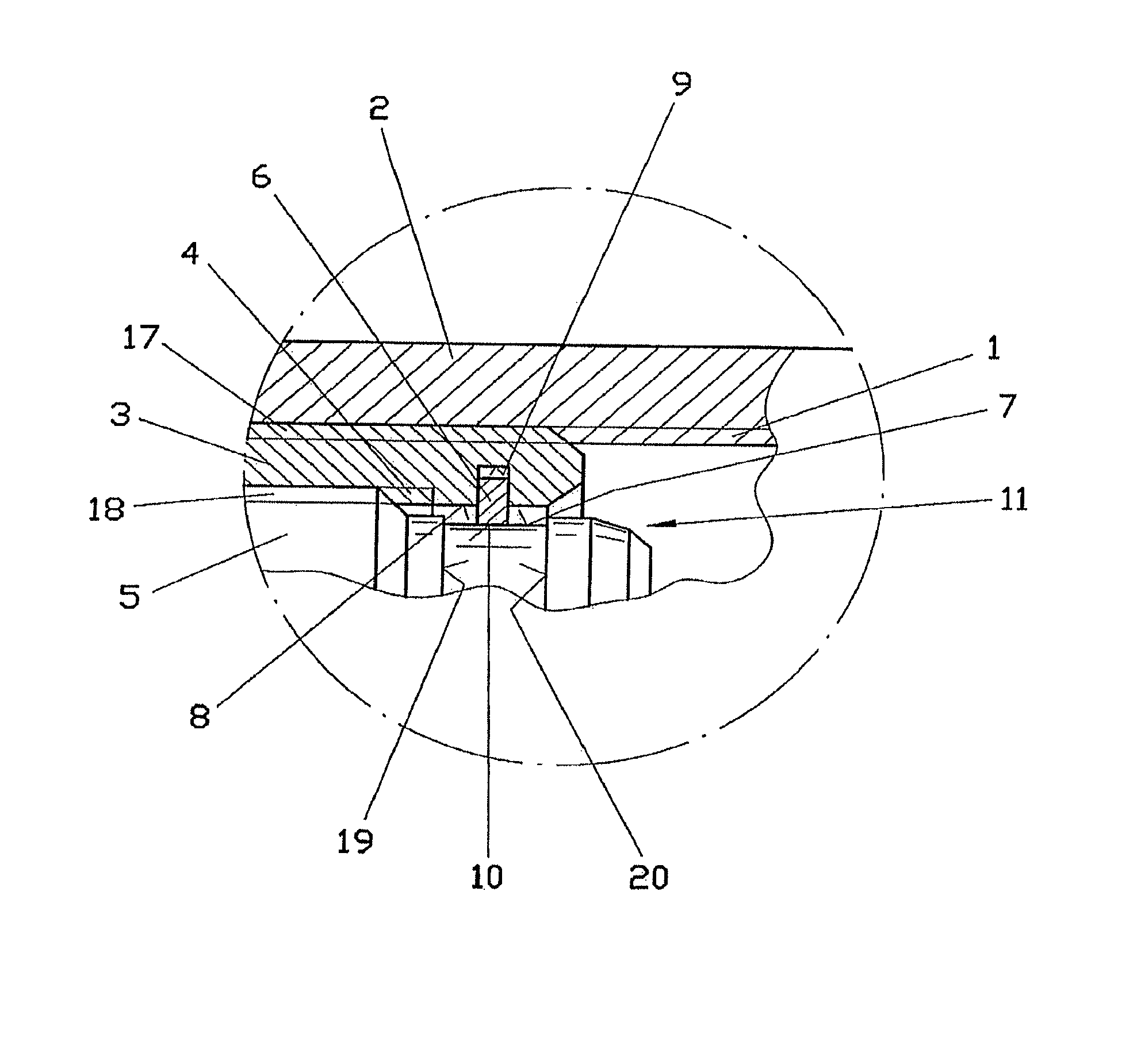
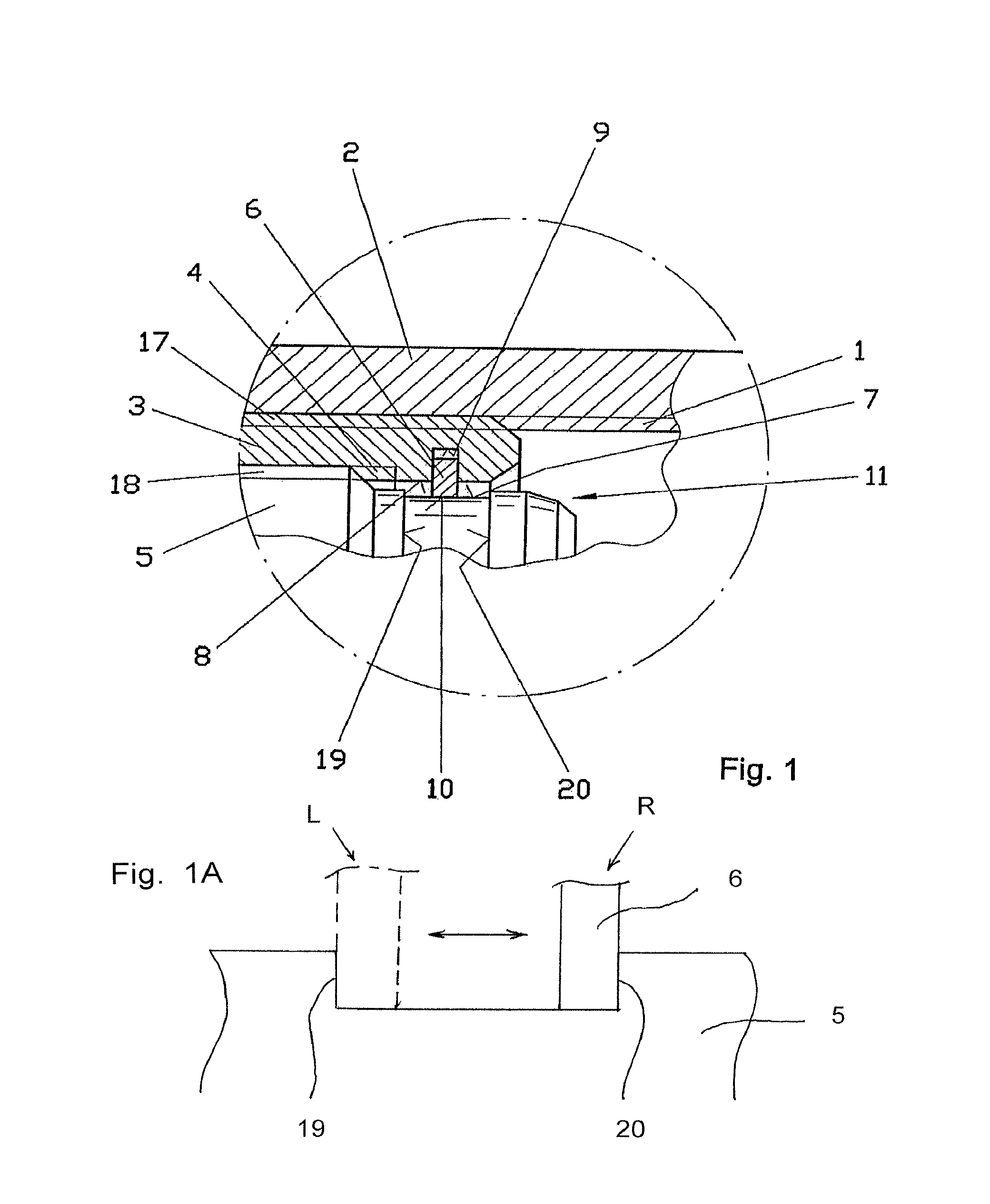
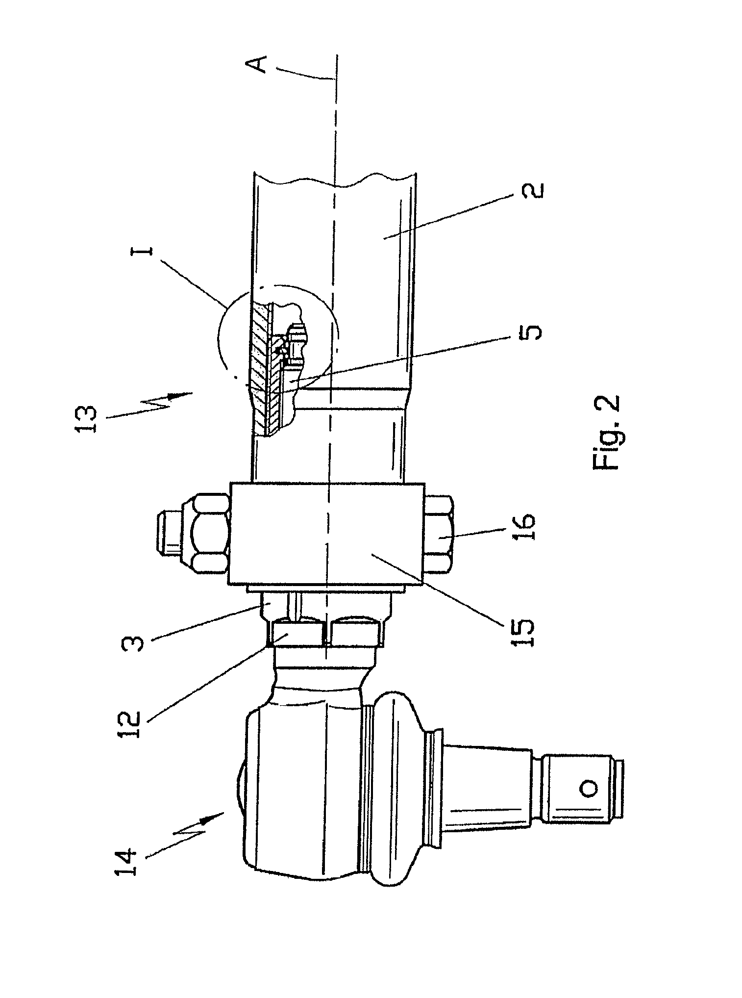
[0022]The enlarged representation of the structural unit according to the invention shown in section in FIG. 1 represents a component part of a tie rod for a motor vehicle. Here, FIG. 1 corresponds to the detail I in FIG. 2.

[0023]The structural unit shown has a tube 2 with an inner thread 1. An adjustment sleeve 3, with an outer thread 17 present at the adjustment sleeve 3 corresponding to the inner thread 1 of the tube 2, is screwed in to this inner thread 1. On its inner lateral surface 8, the inner sleeve 3 has an inner thread 4 which serves for screwing a shank 5 into the adjustment sleeve 3. The shank 5 on its outer lateral surface has an outer thread 18 for this purpose. It is significant for the embodiment of the invention that the inner thread 1 of the tube 2 and the inner thread 4 of the adjustment sleeve 3 are respectively threads implemented running in opposite directions to each other. If, for example, the inner thread 1 of the tube 2 is implemented as a right-hand threa...


PUM


Abstract

A structural unit having a tube (2) which is provided on at least one end with an internal thread (1) which is formed in a first direction of rotation. An adjustment sleeve (3) is screwed into the first end of the internal thread (1) of the tube (2), and the adjustment sleeve (3) has an internal thread (4) which is formed in the opposite direction to the first direction of rotation, and a shank (5) is screwed into the adjustment sleeve (3) and an adjustment travel of the shank (5) is limited by a blocking element (6). The adjustment sleeve (3) supports the blocking element (6) which is located within a groove (7), formed on the outer lateral surface of the shank (5), so as to limit adjustment travel over a range of motion.

Description

[0001]This application is a National Stage completion of PCT / DE2009 / 050019 filed Apr. 7, 2009, which claims priority from German patent application serial no. 10 2008 001 381.1 filed Apr. 25, 2008.FIELD OF THE INVENTION[0002]The invention relates to a structural.BACKGROUND OF THE INVENTION[0003]DE 199 00 264 A1, for example, describes a structural unit of a tie rod for a motor vehicle having a tube provided on at least one side with an inner thread which turns in a first direction of rotation, where an adjustment sleeve that has a corresponding outer thread is screwed into the end of the tube. A shank of a ball joint is screwed into this adjustment sleeve. For this purpose, the shank has an outer thread, which turns in the direction opposite to the first direction that corresponds to the inner thread of the adjustment sleeve. By moving the adjustment sleeve, which has a key surface for attaching a tool for this purpose, the tube and the shank can be moved relative to each other in t...

Claims


Application Information

Patent Timeline
Patent Type & Authority Patents(United States)
IPC IPC(8): F16B3/00
CPCB62D7/20B62D17/00B60G7/001B60G2204/416B60G2206/1112Y10T403/295F16B2200/69
Inventor SOKOLIHS, DIRK
Owner ZF FRIEDRICHSHAFEN AG
Why Eureka
Try Eureka