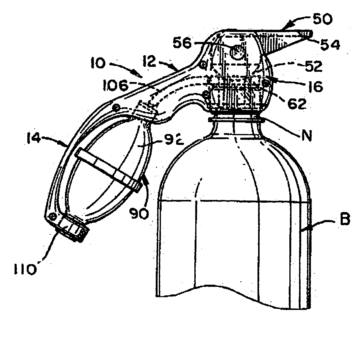
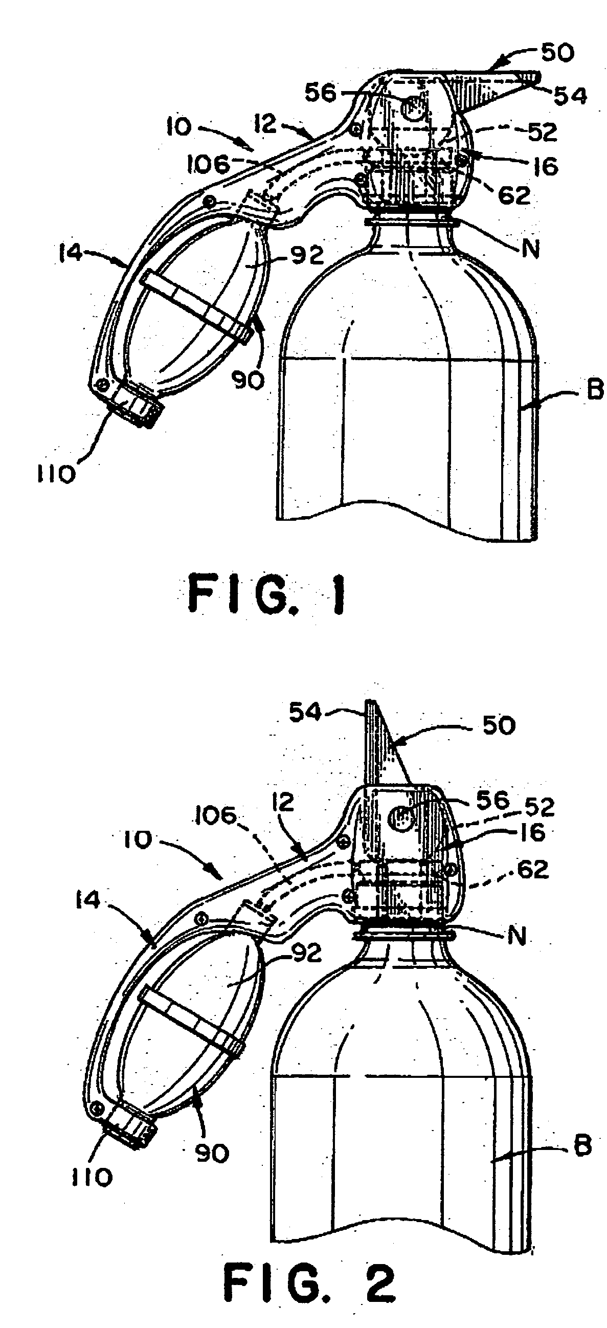
[0011] A pressurizing mechanism is provided for pressurizing the
air space of the container after moving the valve spout from the open position to the closed, sealed position. The pressurizing mechanism includes a hand-operated squeeze
bulb pump fitted to the
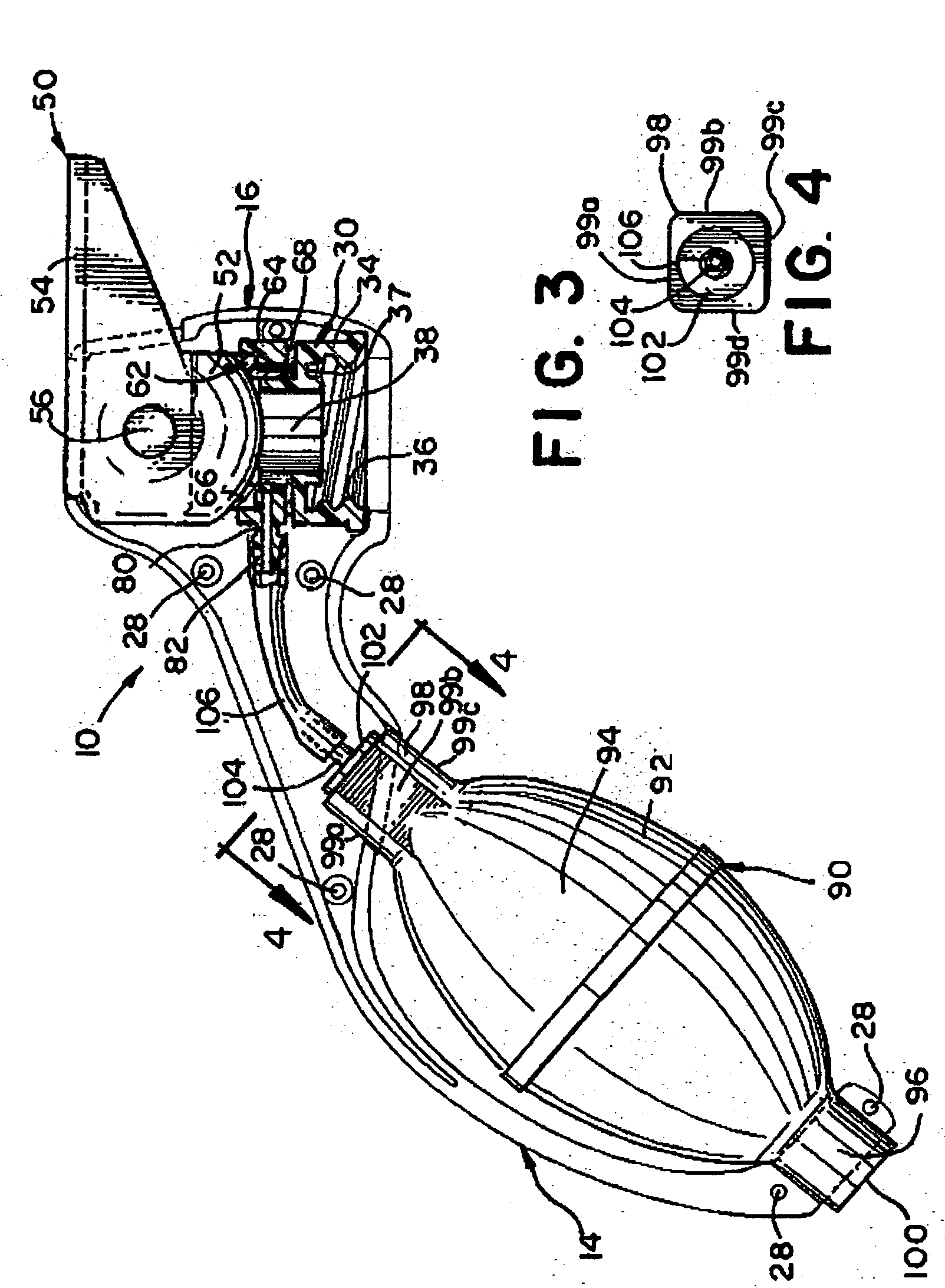
handle portion. The squeeze bulb has a central hollow body surrounding a compressible interior
air chamber, a first end portion and a second end portion. The first end portion of the squeeze bulb is fitted with a one-directional air intake valve member which is structured and disposed to draw air into the compressible interior chamber of the squeeze bulb as the central hollow body is released from the compressed state and returned to a normally relaxed, full shape. The second end portion of the squeeze bulb is fitted with a one-directional air
exhaust valve member which directs air outwardly from the squeeze bulb interior chamber upon compressing the hollow body. A flexible hose connects between the
exhaust valve member on the squeeze bulb and the seal mechanism in the head portion, in air flow communication with the interior
air space of the beverage container. A mechanism is provided for preventing rotation of the squeeze bulb relative to the handle portion. This prevents the flexible hose from becoming twisted and kinked, which would result in blockage of
airflow between the squeeze bulb interior
air chamber and the air space within the beverage container interior.
[0012] When the dispenser device of the present invention is threadably fastened to the neck of the beverage container, a charge of air is introduced into the
bottle interior by repeatedly squeezing and releasing the hand operated squeeze bulb pump on the handle portion until the interior air space within the container is fully pressurized. The fully pressurized condition will be realized when there is increased resistance in compressing the squeeze bulb pump.
Mating engagement of the ball-shaped portion of the valve spout against the
valve seat provides an air and liquid tight seal, holding the air pressure and liquid contents within the beverage container. A integral lever extending from the valve spout facilitates ease of movement of the valve between the closed and open positions. When the valve spout is moved to the open position, the charge of pressurized air is released from the
bottle. While maintaining the valve spout in the open position, the carbonated beverage within the container may be poured by tilting the container so that the neck is angled downwardly, thus allowing the beverage contents to flow through the passage of the valve spout and into a glass or other drinking vessel.
[0013] Yet another embodiment of the present invention is directed to a portable manual
sprayer which may be interconnected and integrally formed to a pump handle that is attachable to a container such as a
bottle. Squeezing the pump handle will direct air into the bottle of the sprayer. A trigger may be fixed to one of two points to include the bottom or top portion of the handle. The trigger is connected to a valve. The pump handle has an air tube connected to a bottle of the sprayer. The bottle of the sprayer has an internal tube that is indirectly connected to the valve. Pressing the trigger will open the valve allowing the liquid to flow out of the
spray nozzle. Releasing or depressing the trigger will close the valve. A
spray volume control is located on the
nozzle for selection between mist and
stream. The pump handle may include a bulb style
air pump that is partially exposed and firmly secured within an ambidextrous handle in a way as to prevent the pump from rotating or
spinning thereby avoiding blockage or kinking of the air tube through which air is pumped into the container. One clear
advantage of the pump handle is that a user can pump air, spray liquid, hold and maintain manual control of the sprayer all at the same time, with the use of one hand.
[0014] The pump handle can serve a multitude of uses. The pump handle can be interconnected and formed integrally for use with many host devices. These devices would include any device that requires a handle and air to flow into the device. The pump handle can also be interconnected and formed integrally for use with devices which require a handle and air to flow into the device with a trigger fitted to perform a specific task or action such as closing and opening a valve. Other attributes of the pump handle sprayer include an ambidextrous handle, pump and trigger; a precise and directional spray control; relatively few pumps will dispense several ounces of liquid; and a compact and portable but yet fairly simple design. Few parts make it highly reliable and simple to produce and manufacture.
[0016] The pump handle equipped sprayer is well suited for spraying chemicals like cleaning solutions,
weed killers, insecticides, etc. With the spray
nozzle on one end and the handle on the opposing far end, there is less chance of the hand coming into contact with hazardous chemicals being sprayed. Since the pump sprayer requires relatively low number of pumps, the risk for a repetitive
work injury is diminished. Further, the pump handle can be attached to the container to create a disposable unit that cannot be opened without damage to the unit, thereby rendering the unit relatively spill-proof and child-proof. These health and safety features give the pump sprayer a plethora of commercial uses.

