A new type of manual adjustment arm with automatic positioning and locking

A technology of automatic positioning and manual adjustment, applied in the field of manual adjustment arm, to achieve the effect of long service life, reduced maintenance cost and convenient assembly

Active Publication Date: 2015-12-09
WM MOTOR TECH GRP CO LTD
View PDF5 Cites 0 Cited by
  • Summary
  • Abstract
  • Description
  • Claims
  • Application Information

AI Technical Summary

Problems solved by technology

[0006] The invention provides a new type of manual adjustment arm that can be automatically positioned and locked to solve the above-mentioned shortcomings of the existing manual adjustment arm.

Method used


Image

  • A new type of manual adjustment arm with automatic positioning and locking
  • A new type of manual adjustment arm with automatic positioning and locking
  • A new type of manual adjustment arm with automatic positioning and locking

Examples


Embodiment 1

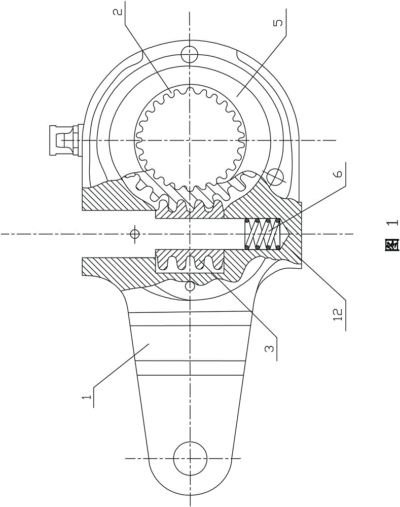
[0030] A new type of manual adjustment arm that can be automatically positioned and locked, refer to Figure 1 to Figure 3 , mainly consists of a housing 1, a worm wheel 2 installed in the housing 1, a worm 3 meshing with the worm wheel 2, and an adjustment shaft 4, and the housing 1 on both sides of the worm wheel 2 is respectively equipped with sealing plates 5. refer to figure 1 , the housing 1 is correspondingly provided with an upper installation hole 11 and a lower installation hole 12 connected with the inner hole of the worm 3, and a pressure spring 6 is arranged in the lower installation hole 12, the pressure spring 6 is made of imported high-quality m steel, elastic Good, it is used to adjust the rotation of axis 4 and position and press, and the effect is good.

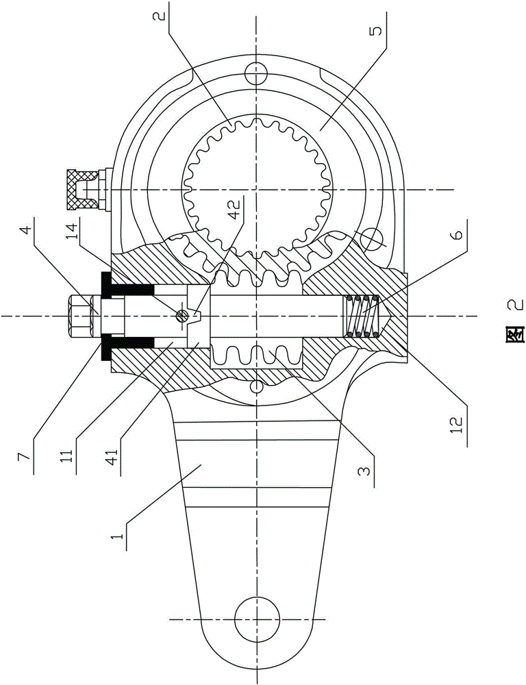
[0031] refer to figure 2 , the adjustment shaft 4 runs through the upper mounting hole 11 , the worm inner hole 3 and the lower mounting hole 12 , its upper end passes through the upper mounting hole 11 ...

Embodiment 2

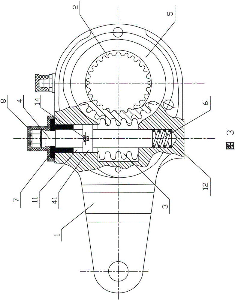
[0043] This embodiment is basically the same as Embodiment 1, the difference is that: the front and rear sides of the housing 1 are symmetrically expanded with a radial threaded hole 13 communicating with the upper mounting hole 11 and corresponding to the tooth groove 42, each M6 column-end set screws 14 are installed in the radially threaded holes 13 , and the ends of the column-end set screws 14 are snapped into the corresponding tooth grooves 42 .

[0044] The above are two specific embodiments of the present invention. The threaded hole 13 is provided only on the housing 1 , not limited to the above two methods, as long as it is located on the housing and cooperates with the tooth groove 42 .


PUM


Abstract

The invention discloses a novel manual adjusting arm capable of being automatically positioned and locked, which comprises a casing, a worm wheel installed in the casing, a worm meshed with the worm wheel, and an adjusting shaft. An upper mounting hole and a lower mounting hole which are penetrating through the inner hole of the worm are correspondingly formed in the casing; an elastic reset device is arranged in the lower mounting hole; the adjusting shaft positioned in the upper mounting hole is provided with a step cylinder; a plurality of tooth spaces with openings in the upper ends are formed in the circumference of the excircle of the step cylinder; at least one radial through hole communicated with the upper mounting hole and corresponding to the tooth space is reamed in the casing; and a positioning shaft with one tail end being clamped or withdrawing from one tooth space is fixed in the radial through hole. The tail end of the positioning shaft of the adjusting arm is clamped into the related tooth space, and the adjusting shaft can not rotate in the radial direction, so that purposes of locking and positioning are achieved; and the only thing to do during adjustment is to push the adjusting shaft, so as to ensure that the positioning shaft is separated from the related tooth space, then brake clearance adjustment can be performed, and after adjustment, the tail end of the positioning shaft is automatically positioned and locked in the related tooth space.

Description

technical field [0001] The invention relates to a manual adjusting arm for adjusting the brake clearance of an automobile brake system, in particular to a new type of manual adjusting arm which can be automatically positioned and locked. Background technique [0002] With the improvement of people's quality of life and the needs of traffic development, cars have become more and more popular, and cars will inevitably vibrate and bump when driving, which often causes the adjustment arm to loosen, thereby affecting the braking effect of the car. Adjustment arm to adjust. [0003] At present, the manual adjustment arm of the automobile brake system used more in the market is to adjust the brake gap by installing springs, steel balls and plum blossom sleeves in the adjustment shaft to adjust and position the brake gap. , the big steel ball spreads out two small steel balls, and the small steel balls are inserted into the plum blossom sleeve to adjust and position the brake. Howe...

Claims


Application Information

Patent Timeline
Patent Type & Authority Patents(China)
IPC IPC(8): F16D65/42
Inventor 李文平李志刚
Owner WM MOTOR TECH GRP CO LTD
Why Eureka
Try Eureka