Suspended gold wire ball bonding workbench

A technology of gold wire ball welding and workbench, which is applied in metal processing equipment, manufacturing tools, welding equipment, etc., can solve the physical damage of chips, gas-sensitive chip positioning, difficulties in clamping and heating, chip positioning, loading and unloading heating and adjustment Difficulties and other problems, to achieve the effect of small physical damage, convenient disassembly and orientation adjustment, and ingenious structure and size design

CN103240561AInactive Publication Date: 2013-08-14NANJING UNIV OF TECH
5 Cites 0 Cited by

Patent Information

Authority / Receiving Office
CN · China
Patent Type
Applications(China)
Current Assignee / Owner
Publication Date
2013-08-14
Estimated Expiration
Not applicable · inactive patent

Smart Images

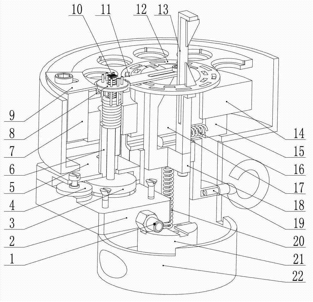
  • Figure 1
    Figure 1
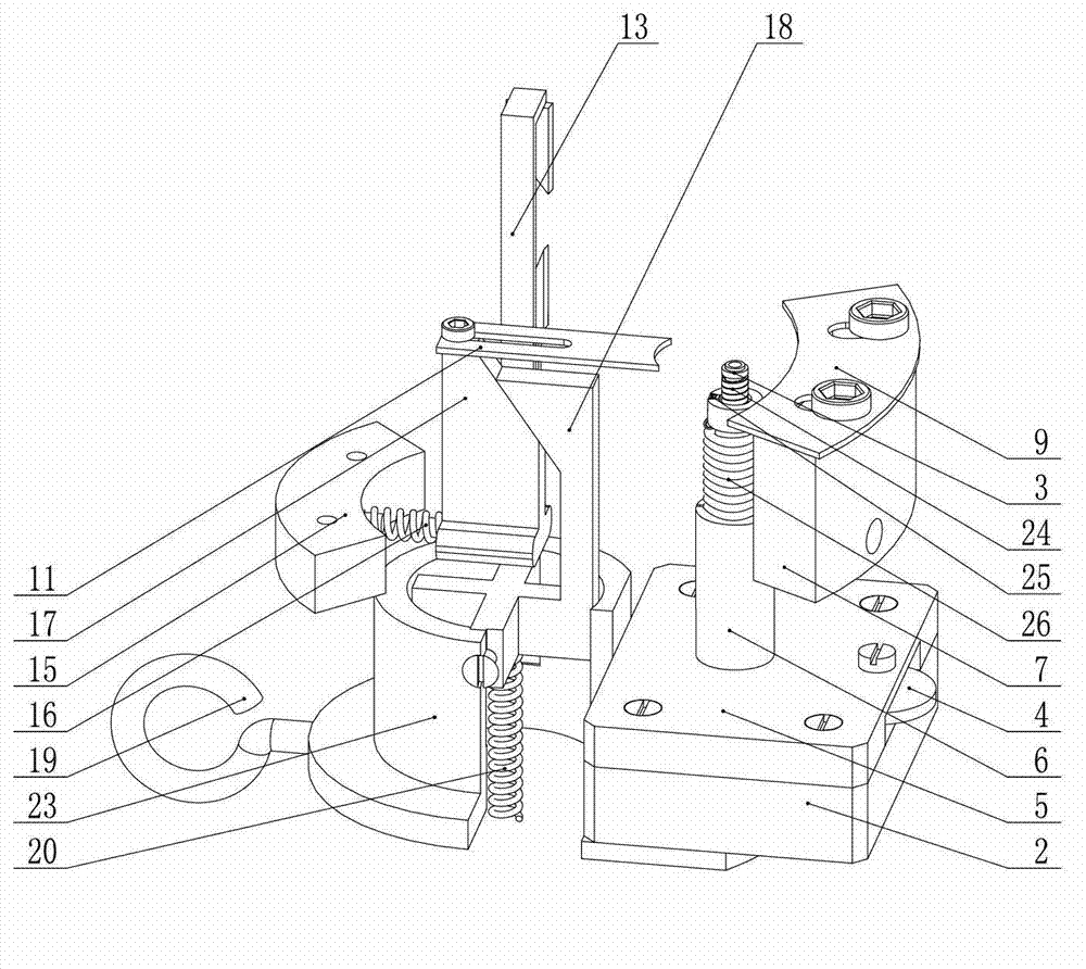
  • Figure 2
    Figure 2
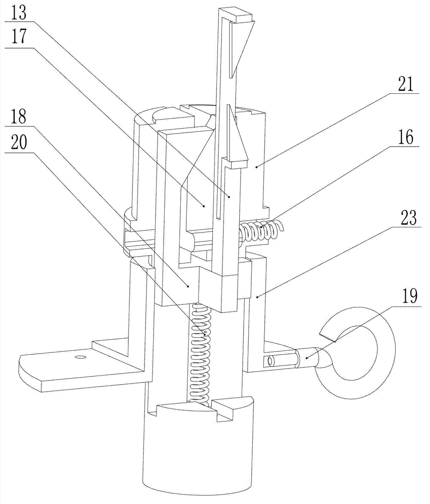
  • Figure 3
    Figure 3
Patent Text Reader

Abstract

The invention discloses a suspended gold wire ball bonding workbench used for connecting a gas sensor chip and a tube shell. The suspended gold wire ball bonding workbench comprises a shell, and a central column, a suction base, a suction column, a heating column, a sliding block, a pressing block, a horizontal compression spring, a vertical compression spring, a pressure plate, a pressure rod, a tube shell movable clamping piece, a tube shell fixed clamping piece and a fixed clamping piece base. The suction base is provided with a suction joint communicated with an outer suction device. The lower portion of the suction column is communicated with the suction base, the top of the heating column is used for placing the chip, and a chip heating solenoid used for heating the chip is arranged at the periphery on the upper portion of the suction column. The heating column is arranged on the outer layer of the suction column, the top of the heating column is used for placing the tube shell, and a tube shell heating solenoid used for heating the tube shell is arranged at the periphery of the upper portion of the heating column. The top of the suction column is higher than that of the heating column. By the suspended gold wire ball bonding workbench, suction fixing is adopted, chip suspended fixing and heating are achieved, disassembly and direction adjustment are facilitated, and physical damages to the chip are less.
Need to check novelty before this filing date? Find Prior Art

Description

technical field

[0001] The present invention relates to a workbench for gold wire ball welding, more specifically, to a heating and fixing workbench for gold wire ball welding in the suspended state of a gas sensor gas sensor chip, which is used to assist a gold wire ball welding machine to transfer gas The pins of the sensitive chip and the shell are connected and fixed by gold wires. Background technique

[0002] At present, gas sensors are widely used in industrial production, daily life, environmental detection and national defense. Thin-film gas sensors have become an important member of gas sensors due to their high sensitivity, fast response, and low operating temperature. In order to make the air flow around the gas sensor chip of the film type gas sensor smooth, and the heating heat is not transmitted to the base of the package shell during operation, the gas sensor chip can be suspended above the base of the package tube. This suspension design brings great diffic...

Examples

Embodiment

[0033] More specifically, as figure 1 , Figure 12 , Figure 5 , Figure 13 and Figure 14 As shown, the gas sensor gas sensor chip suspended gold wire ball welding workbench described in this embodiment includes a shell 22, which is connected to the central column 21 by four screws in the center of the shell; Vertical chute 44, the upper part is provided with horizontal chute 43, and is provided with the supporting platform of two layers of different diameters, and the large-diameter supporting surface place of the lower side of the outer facade of the central column is provided with the lower boss 50 of the central column; A pressing block 18 is set in the straight chute, a slider 17 is set in the horizontal chute, a lifting plate 14 is set above the lower boss 50 of the center column, and an upper boss of the center column is set at the small-diameter support surface on the upper side. 45, the boss 45 on the center column cooperates with the positioning hole 49 provided...