
Rollers, especially track rollers or load rollers for aerial ropeway systems

A technology for carrying rollers and rollers, used in cable railways, shafts and bearings, elements with teeth, etc.

Active Publication Date: 2017-03-01
INNOVA PATENT GMBH
View PDF10 Cites 0 Cited by
  • Summary
  • Abstract
  • Description
  • Claims
  • Application Information

AI Technical Summary

Problems solved by technology

[0004] However, the known device requires considerable additional technical outlay, since the running gear of the cable car additionally has to be embodied with at least one friction wheel

Method used


Image

  • Rollers, especially track rollers or load rollers for aerial ropeway systems
  • Rollers, especially track rollers or load rollers for aerial ropeway systems
  • Rollers, especially track rollers or load rollers for aerial ropeway systems

Examples


Embodiment Construction

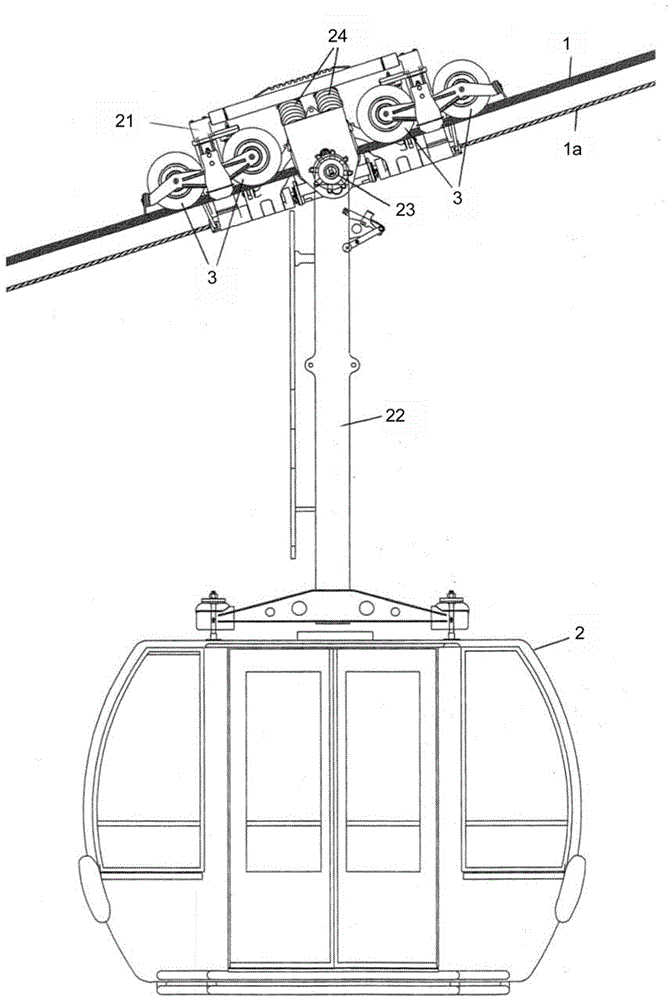
[0027] Referring now to the detailed drawings, first, and in particular figure 1 , a part of an aerial cableway system with a carrying cable 1 , a traction cable 1 a and a cable car 2 is shown here. The cable car 2 of the system is movable along the carrying cable 1 by the traction cable 1a. The aerial cableway 2 is embodied with track rollers 3 mounted on running gears 21 , to which the cable car 2 is fixed via carrying rods 22 , which are movable along the carrying cables 1 . The carrier lever 22 is pivotable on the running gear 21 via a joint 23 about an axis oriented approximately at right angles to the direction of movement and approximately horizontally. The running gear 21 is embodied with a clamping device 24 via which the cable car 2 can be coupled to the traction cable 1a.

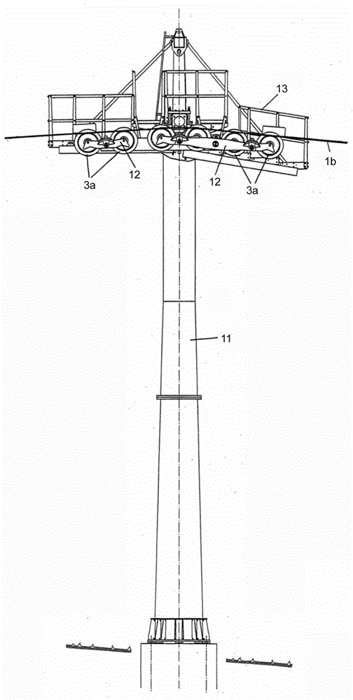
[0028] figure 2 The support 11 of the aerial cableway system is shown, at its upper end a support bearing roller 3a is arranged on a rocker 12 and via which the bearing and transport cables 1...


PUM


Abstract

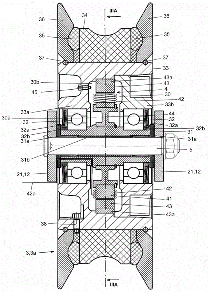
Rollers, in particular track rollers or load bearing rollers for aerial cableway systems, are formed with a cylindrical tube located radially on the inside, two ring bearings located radially outside the tube and at an axial distance from each other , the rollers located radially outside the ring bearing. The roller body is formed as a raceway ring with two flanged disks flanking it. The rollers contain a ring generator located in a cavity surrounded by the roller body and two ring bearings.

Description

technical field [0001] The present invention relates to rollers, in particular to track rollers or load bearing rollers for aerial cableway systems. The roller has a cylindrical tubular part radially on the inside, two ring bearings located radially outside the tubular part at an axial distance from each other, radially outside the ring bearings and embodied as track rings and two ring bearings flanking it. Roller body of a flanged disc. This application claims priority to Austrian Patent Application AT A155 / 2012 filed February 6, 2012 under 35 U.S.C119; the prior application is hereby incorporated by reference in its entirety. Background technique [0002] In a transport system with a vehicle that is movable along a carrying cable or along a guide rail, electrical energy is supplied to the electronic devices located in the vehicle via an accumulator. In that case the accumulator has to be charged at the station of the transmission system, but in a transmission system in w...

Claims


Application Information

Patent Timeline
Patent Type & Authority Patents(China)
IPC IPC(8): B61B12/02
CPCB61B12/02F16C13/00F16H55/50H02K7/08
Inventor P.卢格J·莫里茨休伯
Owner INNOVA PATENT GMBH
Learn More