Composite spinneret and method for producing composite fiber

A composite spinning and polymer technology, applied in spinneret assemblies, fiber processing, textiles and papermaking, etc., can solve the problems of not being able to reach the nanometer level, the distance between holes becomes larger, and the cost of equipment is large, so as to prevent confluence , the effect of high dimensional stability

Active Publication Date: 2015-08-12
TORAY IND INC
View PDF15 Cites 0 Cited by
  • Summary
  • Abstract
  • Description
  • Claims
  • Application Information

AI Technical Summary

Problems solved by technology

[0020] However, since the groove processing is performed around the island component discharge hole 1 and the discharge hole 25, the pitch between the holes becomes large, and the hole filling density cannot be sufficiently increased, making it difficult to manufacture ultra-fine fibers with a fiber diameter of nanometer order. Happening
As described in the examples, since the minimum diameter of the fiber that can be obtained is 1 μm, it cannot reach the nanometer level.
In addition, since the spinneret is subjected to complicated groove processing, time, labor, and cost are required for the manufacture of the spinneret, and there is also a problem that the equipment cost becomes too large in this point.

Method used


Image

  • Composite spinneret and method for producing composite fiber
  • Composite spinneret and method for producing composite fiber
  • Composite spinneret and method for producing composite fiber

Examples


Embodiment 1

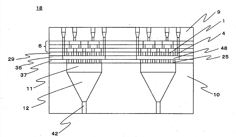
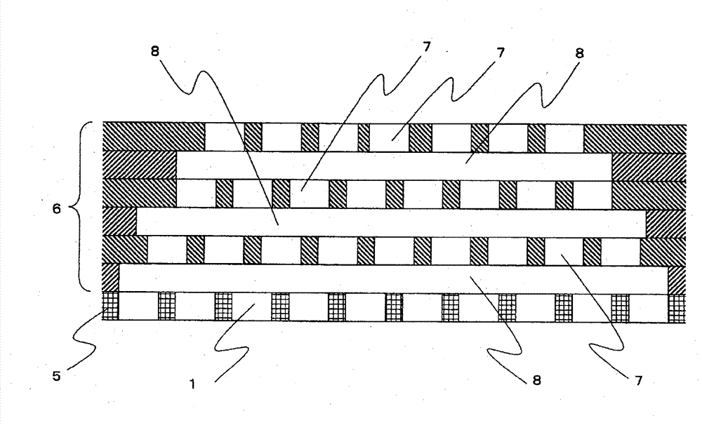
[0269] Polyethylene terephthalate (PET melt viscosity: 120 Pa?s) with an intrinsic viscosity (IV) of 0.63 dl / g as the island component and 5 with an IV of 0.58 dl / g as the sea component polymer -Sodium sulfonate isophthalic acid 5.0 mol% copolymerized PET (melt viscosity of copolymerized PET: 140Pa·s) was melted at 290°C respectively, measured, and flowed into the assembled Figure 6 In the spinning package of the composite spinneret according to this embodiment shown, a sea-island composite polymer stream is discharged from the spinneret discharge holes. In addition, 1,000 island component discharge holes were perforated at equal intervals in one discharge introduction hole for the island component polymer on the distribution plate of the lowest layer. The sea-island ratio is 50 / 50. After cooling and solidifying the discharged composite polymer stream, add an oil agent, and take it up at a spinning speed of 1500m / min, and obtain undrawn fibers of 150dtex-15 fibers (single hol...

Embodiment 2

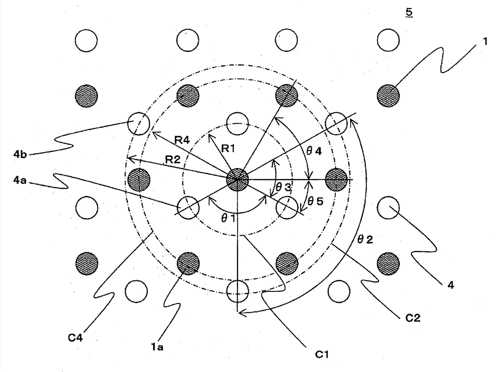
[0272] Such as figure 2 As shown, except that the arrangement of the island component discharge holes and the sea component discharge holes of the distribution plate at the lowest layer is changed to condition B of (2), the same composite spinneret as in Example 1 was used to make the island component polymer ratio ratio Example 1 was larger (the sea-island ratio was set to 20 / 80), but the same polymer as Example 1, the same fineness, and spinning conditions were spun to obtain 13,500 multifibers.

[0273] Here, in the composite spinneret used in Example 2, the radius R1 of the imaginary circumferential line C1 is 0.4 mm, the radius R2 of the imaginary circumferential line C2 is 0.8 mm, and the radius R4 of the imaginary circumferential line C4 is 0.8 mm. An island component discharge hole and a sea component discharge hole with a hole diameter of 0.2 mm were prepared. As described in Table 1, the island component has a triangular cross-section (the angle at the intersection...

Embodiment 3

[0275] Such as image 3 As shown, except that the arrangement of the island component discharge holes and sea component discharge holes of the distribution plate at the lowest layer is changed to condition C of (2), the same composite spinneret as in Example 1 is used, and the sea-island ratio is set to Other than 20 / 80, spinning was performed using the same polymer as in Example 1, the same fineness, and spinning conditions, and 15,000 multifibers were obtained.

[0276] Here, in the composite spinneret used in Example 3, the radius R1 of the imaginary circumferential line C1 is 0.4 mm, the radius R2 of the imaginary circumferential line C2 is 0.8 mm, and the radius R4 of the imaginary circumferential line C4 is 0.693 mm. An island component discharge hole and a sea component discharge hole with a hole diameter of 0.2 mm were prepared. As described in Table 1, the island component has a hexagonal cross-section (the angle at the intersection point of 6 straight lines is 120°)...


PUM

PropertyMeasurementUnit
thicknessaaaaaaaaaa

Abstract

An object is to provide, in the manufacture of islands-in-the-sea composite fibers, a composite spinneret which can prevent the island component polymer streams from joining with one another while increasing the hole packing density of the discharge holes for the island component polymer, and thereby, can form various fiber cross sections, particularly heteromorphic cross sections, with high accuracy while maintaining high dimensional stability of the cross section. The present invention provides a composite spinneret for discharging composite polymer streams composed of an island component polymer and a sea component polymer, which is composed of one or more distribution plates in which distribution holes and distribution grooves for distributing the polymer components are formed; and a lowermost layer distribution plate positioned to the downstream side of the distribution plate in the direction of the polymer spinning path, and having formed therein a plurality of island component discharge holes and a plurality of sea component discharge holes, wherein the sea component discharge holes are arranged on a virtual circular line C1 with a radius R1 centered on the island component discharge hole, the sea component discharge holes are arranged on a virtual circular line C2 with a radius R2 centered on the island component discharge hole, and the island component discharge holes are arranged on a virtual circular line C4 with a radius R4 centered on the island component discharge hole, and R1, R2 and R4 satisfy the following expression (1): (1) R �¢ 2 ‰¥ R �¢ 4 ‰¥ ˆš �¢ 3 × R �¢ 1 and each discharge hole has a predetermined arrangement.

Description

technical field [0001] The invention relates to a composite spinneret and a method for manufacturing composite fibers. Background technique [0002] Fibers using thermoplastic polymers such as polyester and polyamide have excellent mechanical properties and dimensional stability, so they are used in a variety of applications, and a large number of fibers endowed with various functions have been developed. [0003] For example, in the application of clothing, for the purpose of imparting a soft feel, etc., the monofilament is thinned and multi-fiberized, and the monofilament is deformed for the purpose of water absorption, quick-drying improvement, and gloss change. In addition, improvements such as modification of polymers are performed for the purpose of imparting new functions such as realization of vivid dyeing. In addition, in the application of industrial materials, in addition to the fineness of monofilaments, multi-fibers and special-shaped cross-sections of monofila...

Claims


Application Information

Patent Timeline
Patent Type & Authority Patents(China)
IPC IPC(8): D01D4/06D01D5/34
CPCD01D4/06D01D5/36
Inventor 船越祥二水上诚二增田正人
Owner TORAY IND INC
Why Eureka
Try Eureka