Hydraulic buffering adjustable glass clamp

A hydraulic buffering and adjustable technology, applied in the installation of window glass, switches with brakes, door/window accessories, etc., can solve the problems of reducing installation efficiency, increasing installation cost, increasing installation difficulty, etc. Simple, reduced installation costs, and improved safety

Active Publication Date: 2013-09-04
FOSHAN KAWA HARDWARE
View PDF5 Cites 4 Cited by
  • Summary
  • Abstract
  • Description
  • Claims
  • Application Information

AI Technical Summary

Problems solved by technology

But this increases the difficulty of installation, increases the installation cost, and greatly reduces the installation efficiency (especially when installing a large number of glass doors in large shopping malls and hotels)

Method used


Image

  • Hydraulic buffering adjustable glass clamp
  • Hydraulic buffering adjustable glass clamp
  • Hydraulic buffering adjustable glass clamp

Examples


Embodiment 1

[0044] The accompanying drawings are for illustrative purposes only, and should not be construed as limitations on this patent; in order to better illustrate this embodiment, certain components in the accompanying drawings will be omitted, enlarged or reduced, and do not represent the size of the actual product; for those skilled in the art It is understandable that some well-known structures and descriptions thereof may be omitted in the drawings.

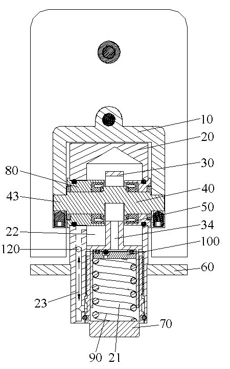
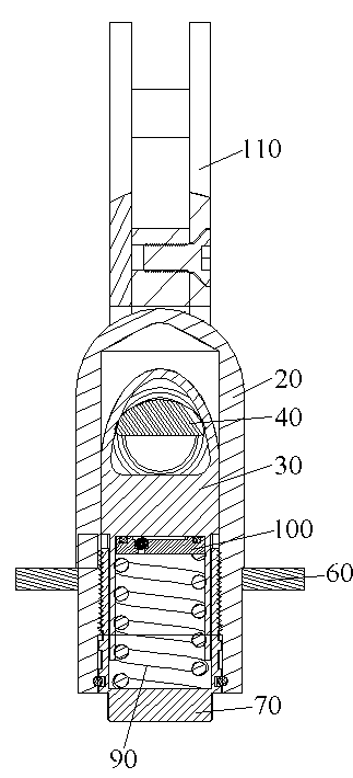
[0045] Such as figure 1 , 2 As shown, a hydraulically buffered adjustable glass clamp includes a movable seat 10 and a panel 110 for clamping the glass door. cylinder liner 70, piston liner 30, protruding shaft 40, spring 90 and one-way throttle valve 100;

[0046] The protruding shaft 40 is rotatably connected with the piston sleeve 30, and the two ends of the protruding shaft 40 are fixed with the movable seat 10; the oil cylinder sleeve 70 is sealed and fixed with the oil cylinder seat 20, and the oil cylinder sleeve 70 is sl...

Embodiment 2

[0061] Such as Figure 16 As shown in -18, the fixed glass 150 is fixed to the wall 130, and the glass door 140 is between the two fixed glasses 150. In this embodiment, the panel 110 is a double-leaf panel, and the two panels 110 clamp the fixed glass 150 and the glass door respectively. 140, the form is suitable for the 180 degree rotation of glass door 140 like this. The working principles of the remaining structures of this embodiment are the same as those of Embodiment 1, and will not be described here.

Embodiment 3

[0063] Such as Figure 19 As shown, the panel 110 is also a double-leaf panel. In this embodiment, it is suitable for the 135-degree rotation of the glass door. The working principle of the rest of the structure of this embodiment is the same as that of Embodiment 2, and will not be described here.


PUM


Abstract

The invention relates to the technical field of glass door clamps, particularly to a hydraulic buffering adjustable glass clamp. According to the hydraulic buffering adjustable glass clamp, a cam shaft is connected with a piston sleeve in a rotation mode; two end portions of the cam shaft are fixed with a flexible seat; an oil cylinder sleeve is fixed with an oil cylinder seat in a sealing mode; the oil cylinder sleeve is sleeved on the lower portion of a piston sleeve; a spring and a one-way throttle valve are arranged inside the piston sleeve; a piston sleeve opening is arranged inside the piston sleeve; the one-way valve enables the piston sleeve opening to be opened or closed; and an oil cylinder first area, an oil cylinder second area, an oil circuit which enables the first oil cylinder first area and the oil cylinder second area to be communicated are arranged inside a cylinder body of the oil cylinder seat. The hydraulic buffering adjustable glass clamp has the advantages of automatically and slowly closing with constant speed when the door closing angle is smaller than 90 degrees; enabling the returning speed to be regulated through speed adjustment screws; being free of acceleration close when coming across exogenic action in the closing process; having functions of speed reduction and speed buffering to improve safety; enabling the appearance size to be controlled as a traditional spring type return hinge; being simple and attractive; being simple to install; and enabling the construction cost to be reduced.

Description

technical field [0001] The invention relates to the technical field of glass door clips, and more specifically, to an adjustable glass clip with hydraulic buffer. Background technique [0002] With the development of science and technology, glass doors have appeared in various occasions in society, such as shopping malls, office buildings, stations, hotels, homes, etc. For a long time, the glass clips on glass doors have been using general hinges and springs Type glass clip. After opening the glass door with ordinary hinges, people have to manually close it by hand, which is extremely inconvenient and wastes time; and although the glass door with spring type glass clip has automatic closing function, it cannot control the closing speed. , because the speed at which it closes is controlled by the size of the spring force, and the spring force usually rebounds quickly, making the closing speed also fast. If the people behind are not paying attention, they will be hit, which la...

Claims


Application Information

Patent Timeline
Patent Type & Authority Applications(China)
IPC IPC(8): E05F3/20E05F3/04E05F3/22E06B3/58
Inventor 陈自强
Owner FOSHAN KAWA HARDWARE
Why Eureka
Try Eureka