Rolling bearing

A technology of rolling bearings and bearings, which is applied in the direction of ball bearings, bearing components, shafts and bearings, etc., and can solve the problems of large radial size, low life, loud noise, etc.

Inactive Publication Date: 2021-07-06
宣荣康
View PDF0 Cites 0 Cited by
  • Summary
  • Abstract
  • Description
  • Claims
  • Application Information

AI Technical Summary

Problems solved by technology

[0002] Rolling bearing is a precision mechanical element that changes the sliding friction between the running shaft and the shaft seat into rolling friction, thereby reducing friction loss. Rolling bearings are generally composed of inner rings, outer rings, rolling elements and cages. The function of the ring is to cooperate with the shaft and rotate together with the shaft; the function of the outer ring is to cooperate with the bearing seat and play a supporting role; the rolling elements are evenly distributed between the inner ring and the outer ring by means of the cage, and its The shape, size and quantity directly affect the performance and life of the rolling bearing; the cage can evenly distribute the rolling elements, guide the rolling elements to rotate for lubrication, support the rotating shaft and the parts on the shaft, and maintain the normal working position and rotation accuracy of the shaft , Rolling bearings are easy to use and maintain, reliable in operation, good in starting performance, and have a higher carrying capacity at medium speeds. Compared with sliding bearings, rolling bearings have larger radial dimensions, poorer vibration damping capabilities, lower life at high speeds, and louder noise
[0003] In the process of carrying out the bearing lubrication simulation experiment, the lubrication degree of the shaft part of the bearing will be adjusted through the resistance structure, so as to achieve the function of testing the parameters of the lubrication degree experiment, but the adjustment of the lubrication degree for the local area is not convenient enough, and the lubrication degree In the worst case, the loss of the bearing is greater, resulting in a higher loss rate of the bearing during the experiment

Method used


Image

  • Rolling bearing
  • Rolling bearing
  • Rolling bearing

Examples


Embodiment Construction

[0028] The following will clearly and completely describe the technical solutions in the embodiments of the present invention with reference to the accompanying drawings in the embodiments of the present invention. Obviously, the described embodiments are only some, not all, embodiments of the present invention. Based on the embodiments of the present invention, all other embodiments obtained by persons of ordinary skill in the art without making creative efforts belong to the protection scope of the present invention.

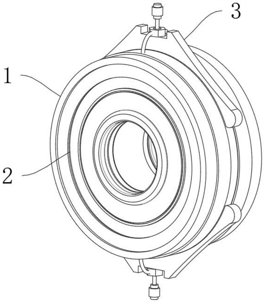
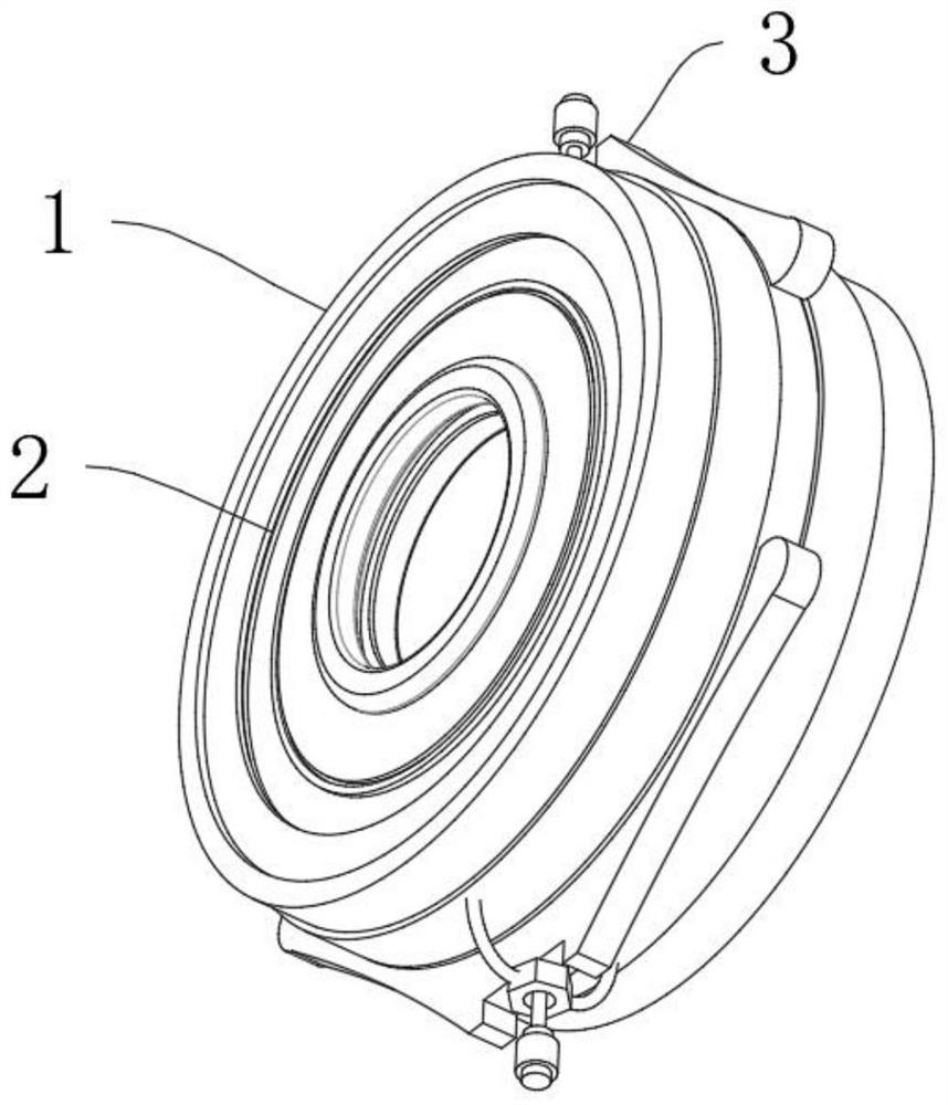
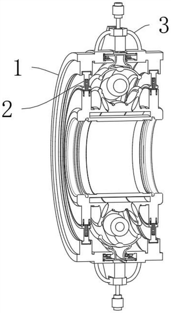
[0029] Refer to the attached Figure 1-7 , an embodiment provided by the present invention:

[0030]A rolling bearing, comprising a bearing frame body mechanism 1 for lubricity experiments, detachable dust-proof components 2 are inserted on both sides of the outer wall of the bearing frame body mechanism 1 for lubricity experiments, and the bearing frame body mechanism 1 for lubricity experiments An adjustable lubrication and damping simulation mechanism 3 is...


PUM


Abstract

The invention discloses a rolling bearing, and particularly relates to the field of bearings. The rolling bearing comprises a bearing frame body mechanism for a lubrication degree experiment, detachable dust-proof assemblies are inserted into the two sides of the outer wall of the bearing frame body mechanism for the lubrication degree experiment, and an adjustable lubrication damping simulation mechanism is fixedly installed outside the bearing frame body mechanism for the lubrication degree experiment; and the adjustable lubrication damping simulation mechanism comprises a second reserved type movable empty groove, and the second reserved type movable empty groove is formed in the bearing frame body mechanism for the lubrication degree experiment. By arranging the adjustable lubrication damping simulation mechanism, the supporting type bearing air pressure cavity is pushed to extrude the outer walls of rolling type collision beads, resistance of different degrees is generated on the rolling type collision beads, the lubrication degree adjustment effect is achieved, and the convenience and controllability of local adjustment of the lubrication degree are relatively improved.

Description

technical field [0001] The invention relates to the technical field of bearings, and more specifically, the invention relates to a rolling bearing. Background technique [0002] Rolling bearing is a precision mechanical element that changes the sliding friction between the running shaft and the shaft seat into rolling friction, thereby reducing friction loss. Rolling bearings are generally composed of inner rings, outer rings, rolling elements and cages. The function of the ring is to cooperate with the shaft and rotate together with the shaft; the function of the outer ring is to cooperate with the bearing seat and play a supporting role; the rolling elements are evenly distributed between the inner ring and the outer ring by means of the cage, and its The shape, size and quantity directly affect the performance and life of the rolling bearing; the cage can evenly distribute the rolling elements, guide the rolling elements to rotate for lubrication, support the rotating sha...

Claims


Application Information

Patent Timeline
Patent Type & Authority Applications(China)
IPC IPC(8): F16C19/16F16C33/58F16C33/66F16C33/78
CPCF16C19/16F16C33/58F16C33/66F16C33/78F16C33/7806F16C33/7816
Inventor 宣荣康
Owner 宣荣康
Why Eureka
Try Eureka