Method of Reducing Surface Resistance Based on Plasma Exciting Device

A plasma and excitation device technology is applied in the field of reducing surface resistance based on the plasma excitation device, which can solve the problem of increasing the stall angle of attack, unable to effectively reduce the turbulent frictional resistance, and unable to interfere with the underlying pseudo-sequence structure of the turbulent boundary layer. and other problems to achieve the effect of reducing the frictional resistance of turbulent flow

Inactive Publication Date: 2016-01-13
SHANGHAI JIAO TONG UNIV
View PDF12 Cites 0 Cited by
  • Summary
  • Abstract
  • Description
  • Claims
  • Application Information

AI Technical Summary

Problems solved by technology

[0005] After searching the existing technologies, the article "Influence of Plasma Pneumatic Actuator Layout on Discharge Characteristics and Acceleration Effect" published in "Nuclear Fusion and Plasma Physics" in June 2008 recorded three kinds of plasmas: semicircle, sawtooth, and conventional Volume actuator layout technology, but in this technology, plasma actuators can be used to increase the stall angle of attack, reduce flow separation and suppress noise, but cannot effectively reduce turbulent frictional resistance
[0006] In addition, the article "PIV Measurement of Plasma-Induced Cone Precursor Flow Field" published in "Journal of Applied Mechanics" in June 2011 records the experimental process of plasma actuator combined with duty cycle technology to achieve mechanical control, and also discloses The control effect at different phase angles and frequencies, but the control of the duty cycle and phase angle of this technology cannot induce the spanwise periodic oscillation of the flow, and cannot disturb the quasi-ordered structure at the bottom of the turbulent boundary layer

Method used


Image

  • Method of Reducing Surface Resistance Based on Plasma Exciting Device
  • Method of Reducing Surface Resistance Based on Plasma Exciting Device
  • Method of Reducing Surface Resistance Based on Plasma Exciting Device

Examples


Embodiment 1

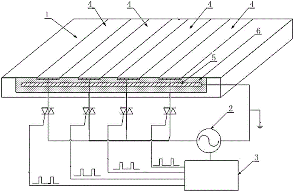
[0031] Such as figure 1 As shown, the device of this embodiment includes: an electrode array arranged on the target plane 1, a power source 2 and a controller 3 for adjusting the parameters of the power source 2, wherein:

[0032] The electrode array includes: a number of exposed electrodes 4 arranged in parallel on the surface of the target plane 1, a buried electrode 5 disposed inside the target plane 1, and an insulating medium 6 disposed between the exposed electrodes 4 and the buried electrodes 5, wherein: The centerlines of the exposed electrode 4 and the embedded electrode 5 are parallel to the incoming flow direction of the turbulent flow;

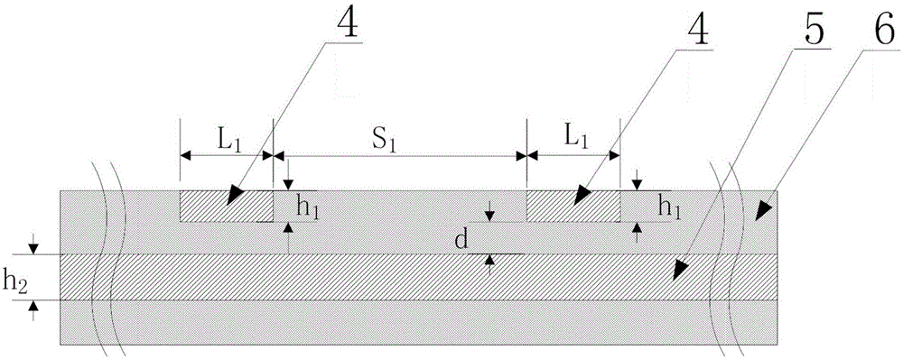
[0033] Such as figure 2 As shown, the structure of the buried electrode 5 is: a monolithic structure whose width includes the entire width of the exposed electrode 4 to generate synchronous induced fluid without phase difference.

[0034] Compared with the prior art, in this embodiment, the adjacent electrodes can generate oppos...

Embodiment 2

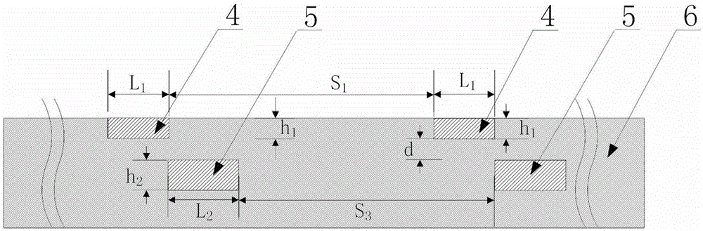
[0044] Such as image 3 As shown, other structures are the same as in Embodiment 1, and the structure of the buried electrode 5 is: a single-side separated structure that is separated into several units and respectively arranged on one side of each exposed electrode 4, wherein: the single-side separated structure In the structure, each embedded electrode 5 unit and each exposed electrode 4 are distributed alternately, and the positions of the respective broad sides of the two electrodes correspond to generate an asynchronous and different-phase induced fluid. In the figure, the width of each embedded electrode 5 unit is L 2 , the spacing between each unit is S 3 .

[0045] Such as Figure 5 , Figure 6 and Figure 7 As shown, the topological structure of the exposed electrode 4 is: a straight line parallel structure, a zigzag structure or a curved structure.

[0046] In the drag reduction method of this embodiment, on the premise that each electrode array can be stably d...

Embodiment 3

[0048] Such as Figure 4 As shown, the other structures are the same as in Embodiment 1, and the structure of the buried electrode 5 is: a double-side separated structure separated into several units and arranged on both sides of each exposed electrode 4, in which one exposed The electrodes 4 respectively correspond to two embedded electrode 5 units, and the wide sides on both sides of the exposed electrode 4 respectively correspond to the broad sides of one embedded electrode 5 unit. At this time, a synchronous induction fluid with no phase difference or an asynchronous out-of-phase is generated. In the figure, the distance between the units of embedded electrodes 5 corresponding to different exposed electrodes 4 is S 2 .

[0049] Such as Figure 5 , Figure 6 and Figure 7 As shown, the topological structure of the exposed electrode 4 is: a straight line parallel structure, a zigzag structure or a curved structure.

[0050] The drag reduction method in this embodiment c...


PUM


Abstract

The invention discloses a method for reducing the surface resistance based on a plasma exciting device in the technical field of power of aircraft or ground transportation. Through an electrode array arranged on a target plane, a power supply and a controller used for regulating a parameter of the power supply, and different working states of the controller, a period controllable induced fluid is generated on the inner layer of a turbulent boundary layer on the surface of a solid, a bursting process and a downward-sweeping process of the inner layer of the turbulent boundary layer are interfered, the generation and the propagation of a coherent structure and a low-speed streak of the inner layer of the turbulent boundary layer are inhibited, and the effect of reducing the turbulent friction resistance on the surface of the solid is achieved. The plasma exciting device is capable of effectively inhibiting the turbulent friction resistance under a high reynolds number, has the characteristics of simple structure, low energy consumption, stable performance and no additional load, is capable of being actively regulated, and is suitable for a larger inflow velocity without additional parasite drag.

Description

technical field [0001] The present invention relates to a method used in the power technology field of aircraft or ground transportation, in particular to a method for reducing surface resistance based on a plasma excitation device. Background technique [0002] Turbulent frictional resistance is one of the main resistances in aviation vehicles and ground vehicles, which directly affects the economy and environmental protection of aircraft and ground vehicles. Due to the high Reynolds number, the flow near the wall transforms from a laminar flow state to a turbulent flow state, which makes the frictional resistance on the solid surface increase nonlinearly, forcing a substantial increase in the total resistance; More than 50% of the resistance is the key to reducing the total resistance. Therefore, the reduction and control of turbulent frictional resistance can greatly save fuel or power consumption costs, and can increase the operating speed of aircraft and ground vehicle...

Claims


Application Information

Patent Timeline
Patent Type & Authority Patents(China)
IPC IPC(8): B64C23/00B62D37/02B61D17/00
Inventor 李伟鹏
Owner SHANGHAI JIAO TONG UNIV
Why Eureka
Try Eureka